• WANTED: Happy members who like to discuss audio and other topics related to our interest. Desire to learn and share knowledge of science required. There are many reviews of audio hardware and expert members to help answer your questions. Click here to have your audio equipment measured for free!

Pyle PT8000CH Multichannel Amplifier Teardown

OP
amirm

amirm

Founder/Admin
Staff Member
CFO (Chief Fun Officer)
Joined
Feb 13, 2016
Messages
44,657
Likes
240,865
Location
Seattle Area
Amir, thank you for this. A question to you (and the membership) : when you were in there inspecting and looking around, what did you think of the build quality? How confident are you that this amp would last five years under 'normal' operating conditions?
Hard to predict given the no-name caps, and transistors with no branding. Repair would be hard too given lack of marking on the transistors.

Cooling is good though. So I would guess 3 to 5 years of life.
 

HarmonicTHD

Major Contributor
Joined
Mar 18, 2022
Messages
3,326
Likes
4,835
Wow. Just the two toroidal transformers come close (2/3 maybe) to the sales price if one would buy them individually. Plus case plus heatsinks and connectors. If one would need cheap parts for a diy amp project buy this amp and take out the amp modules and put in your own. Amazing
 

dfuller

Major Contributor
Joined
Apr 26, 2020
Messages
3,406
Likes
5,252
[Goes directly into strategies for lowering noise and distortion...]

Interesting how many of the resistors are carbon film instead metal film. I wonder of any of those e-caps are DC coupled and could be replaced with poly? I also wonder what the spec on the output transistors is? For maybe $100, this could possibly be turned into a contender. Too bad I don't have an Audio Precision on my bench. I would be very tempted...
On top of this... I think just increasing global feedback by a few dB would drop distortion considerably. I agree with you re: noise, looks to be mostly random so probably resistor noise and maybe not particularly low noise discretes.
 

GaryRamu

Member
Joined
Dec 11, 2023
Messages
5
Likes
0
Lost ch7-ch8 on this less than 2 year old amp---from reading thread, suspect bad transistor possibly after fan stopped. Not sure what caused failure. One day good, next day bad.

Any ideas on best how to confirm before I get started down wrong path?

Am new to audio amp repair starting as hobby and have a 50 year old amp out of old juke box am working on also, entirely different beast. Have oscilloscope and plenty of tools.

My amp (same model) is different than the one discussed here. Notice heat sink on mine has what looks like 4 round power transistors, 2 on each sink. It is distinctly different is other ways also. See photo.
Ch7-Ch8_bad_PT8000CH.jpg


Any advice greatly appreciated.
 
Last edited:

GaryRamu

Member
Joined
Dec 11, 2023
Messages
5
Likes
0
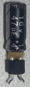
BadCap47uF.jpg Waited for a response on advice from this group to help fix this amp. Received near nothing since posting last December 10, 2023. Embarked on my first dive into fixing this interesting powerful amplifier.

Began with visual inspection which I can say was lacking as did not spot this blown cap supporting input on ch7 until several days later while re-acquainting self with new scope have not touched in months.

Both ch7 and ch8 are dead at output, but, ch8 is alive and well all the way to an 8 pin relay at output which apparently---simultaneously switches both ch7 and ch8 if logical conditions following voltages I can imagine are not met per circuit immediately adjacent to this relay.

If correct logic is met, audio output is switched on for both ch7 and ch8. Understandably, is switched off if not as can result in damaged speakers and other potential roasting while loaded.

Confirmed ch7 is toast so no matter what with ch8, it is also down as logic addresses either channel and switches both off at relay if one is not in specification.

The metal case on capacitor had nearly popped completing off for ch7, can't be helping leaving it that way....see if you can spot the blown capacitor at input for ch7, stands taller, since is popped, than all others which are level with each other.

A few notes:

1.) As noted not the case by author stating unmarked transistors, I found transistors are marked where each channel has a PNP/NPN pair per channel with a pre-amp pair and power amp pair at big heat sink.

The voltages at the pre-amp for ch7 are 6 and 14 volts (collector, emitter) and near 53 volts at base. The collector and emitter voltages are way out of range compared to that of all other functioning channels.

2.) All the the onboard input connectors for each channel appear to be glued into place! Attempted to disconnect, did not wish to force, leaving connected for now.

Ordering a replacement capacitor tonight, any advice on troubleshooting appreciated.
 
Last edited:
Top Bottom