
-
WANTED: Happy members who like to discuss audio and other topics related to our interest. Desire to learn and share knowledge of science required. There are many reviews of audio hardware and expert members to help answer your questions. Click here to have your audio equipment measured for free!
You are using an out of date browser. It may not display this or other websites correctly.
You should upgrade or use an alternative browser.
You should upgrade or use an alternative browser.
Pre-ringing with linear phase room EQ filters
- Thread starter Krunok
- Start date
Had the same ideaIt would be interesting though to see difference in spectrum

DeltaWave should reveal that.
Uli's track splitted into two section (1st four, 2nd four) gives this in DeltaWave:
- the split was not perfect - DeltaWave should handle that
- while to 1st four (blue) have max. value to the negative side, the 2nd four (white) have that in opposite direction
- there are people claiming that polarty can be detected by listening
- looks like the clips in the second have are a bit longer than in the first half
- any proposal what is caused be the pre-ringing?
DDF
Addicted to Fun and Learning
- Joined
- Dec 31, 2018
- Messages
- 617
- Likes
- 1,360
If there is too much pre-ringing you will recognize it. So e.g. a simple drum hit = tok may sound like whoop-tok.
Indeed. Easily heard here:
https://www.audiomasterclass.com/ne...se-eq-on-transient-signals-such-as-snare-drum
EQ applied was aggressive but could be in the realm of possibility for heavy handed FIR eq of a narrow room mode.
Pio2001
Senior Member
The most sensitive signal for pre-ringing should be the CEA 2010 burst that you can generate with REW.
Pre-ringing can be important in the case of a full spectrum automatic room correction in linear phase version. Even with small correction, these corrections may feature some very small ripples.
For example, this linear phase correction :

Produces this preringing on the 2000 Hz CEA burst (top: original, bottom: corrected, left and right).

Pre-ringing can be important in the case of a full spectrum automatic room correction in linear phase version. Even with small correction, these corrections may feature some very small ripples.
For example, this linear phase correction :
Produces this preringing on the 2000 Hz CEA burst (top: original, bottom: corrected, left and right).
- Thread Starter
- #25
Had the same idea
DeltaWave should reveal that.
Uli's track splitted into two section (1st four, 2nd four) gives this in DeltaWave:
View attachment 47706
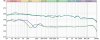
Not sure whether looking at the spectra makes sense under this circumstances - anyhow, see both spectra here:
- the split was not perfect - DeltaWave should handle that
- while to 1st four (blue) have max. value to the negative side, the 2nd four (white) have that in opposite direction
- there are people claiming that polarty can be detected by listening
- looks like the clips in the second have are a bit longer than in the first half
View attachment 47708
Ulli
- any proposal what is caused be the pre-ringing?
There was no change in spectrum as both filters have the same magnitude settings.
solderdude
Grand Contributor
The secret is indeed in the time domain not in the amplitude or frequency domain.
Just have a listen to the resulting null.
That is the difference (do not use gain on the resulting null)
It is something that could be fun to see in dF @Serge Smirnoff ?
Just have a listen to the resulting null.
That is the difference (do not use gain on the resulting null)
It is something that could be fun to see in dF @Serge Smirnoff ?
- Thread Starter
- #27
The secret is indeed in the time domain not in the amplitude or frequency domain.
Just have a listen to the resulting null.
That is the difference (do not use gain on the resulting null)
The true secret is how to do phase correction to avoid pre-ringing.
6speed
Active Member
Indeed. Easily heard here:
https://www.audiomasterclass.com/ne...se-eq-on-transient-signals-such-as-snare-drum
EQ applied was aggressive but could be in the realm of possibility for heavy handed FIR eq of a narrow room mode.
That is another good example, but is there a way for us to look at the pre-ringing of an impulse response and predict whether music will have an audible whoop? The threshold of audibility...how much pre-ringing is allowed to precede the peak, what amplitude is allowed, etc.
That would be step 1, and step 2 would be practical rules of thumb e.g. screenshots of an app like rePhase where we say it's OK to correct one wiggle back to flat but not another because the correction will be audible.
- Thread Starter
- #29
That is another good example, but is there a way for us to look at the pre-ringing of an impulse response and predict whether music will have an audible whoop? The threshold of audibility...how much pre-ringing is allowed to precede the peak, what amplitude is allowed, etc.
That would be step 1, and step 2 would be practical rules of thumb e.g. screenshots of an app like rePhase where we say it's OK to correct one wiggle back to flat but not another because the correction will be audible.
IR will show HF pre-ringing, step response will show pre-ringing with lower frequencies.
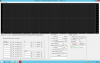
I had to remove every single phase correction filter and leave only crossover phase linearization to get rid of pre-ringing. This is how it looks now:
6speed
Active Member
@Krunok Now that you have removed all pre-ringing, can you hear a difference? Either
- It sounds worse because you have removed a lot of corrections
- It sounds better because you did not realize the pre-ringing was detrimental
- It sounds no better or worse (but maybe different) because you lost some corrections, but the pre-ringing had not been excessive
- Thread Starter
- #31
@Krunok Now that you have removed all pre-ringing, can you hear a difference? Either
- It sounds worse because you have removed a lot of corrections
- It sounds better because you did not realize the pre-ringing was detrimental
- It sounds no better or worse (but maybe different) because you lost some corrections, but the pre-ringing had not been excessive
I didn't change magnitude response filters so general sound impression remained the same.
Pre-ringing related artifacts are gone and that is audible.
GD graph lookse a little bit worse but I can't hear the difference.
6speed
Active Member
At least you were able to retain crossover phase linearization. Do you have a simple 2way?
- Thread Starter
- #33
At least you were able to retain crossover phase linearization. Do you have a simple 2way?
Yes, LR4 at 1800Hz.
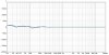
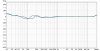
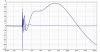
Don't know if this adds anything to this thread but Mathaudio Room EQ avoids pre echo (pre-ring). I really don't know if this has any effect of measurement results however Mathaudio stated that the absence or pre echo ensures the neutrality of the sound . https://mathaudio.com/room-eq.htmFor quite some time I was using minimum phase room EQ filters tha I generated mannually with rePhase, but recently I decided to apply full scale time domain correction and go for linear phase response. As a result I got pretty nice looking phase, GD and step response graphs (measured at LP, 4m away from speakers):
View attachment 47650
View attachment 47651
View attachment 47652
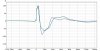
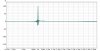
As a side effect I also got some pre-ringing in my filters which is visible in IR:
Left
View attachment 47654
Right
View attachment 47655
That pre-ringing visible before IR got me worried a little, especially as I was not able to find any relevant data on the Netabout audibility of pre-ringing artefact. And no, I cannot hear any nasty effects after I adjusted phase - subjectively I would say sound got better, but of course it's impossible to tell that without a proper blind test.
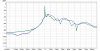
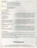
Anyway, what I did found was an IR response of Topping D10 posted on this forum:
View attachment 47657
What surprised me is how similar it looks to IR of my speakers, both in terms of shape and in terms of pre-ringing. Based on that my conclusion was that pre-ringing with my room EQ filters is very acceptable, so nothing to fear off.
What are your thoughts/comments on this?
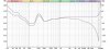
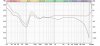
I'm looking after Room correction software comparisons to obtain the best possible measurement. I tried REW but for what ever reason can't get a good reading with my mic + i find it way to complex to use it in combination with Foobar2000. But if results, better, different or similar i will put more effort in to it so i can compare. Did people make comparisons between different sort of Room correction software.? Or is there an article that objectively tested several Room correction software?. On the other hand Mathaudio Room EQ let you determine your preferd target curve by using a slider an let you draw your own preferd curve. For my IMF close monitors I make use of this possibility for my Vandersteen full range speakers I'm not an prefer the flat target curve. Does it matter if certain room correction software are handling pre echo or avoids overcompensation (see the deep notch around 150 hz for my IMF's) as Mathaudio does?? So I guess it is difficult to make comparisons between several room correction software an certain functionalities that some have or have not.
IMF monitors:

Vandersteen model 1

Last edited:
6speed
Active Member
Apparently Krunok has disappeared, but as another reference point, here are the impulse and step responses I ended up with for my recent 3 way build. I am using FIR LR2 crossovers at 300 and 2.5kHz with only 1024 taps each, and no additional FIR corrections. I do see a pre...let's say disturbance, but not a pre-ringing problem.


vavan
Senior Member
nope, he simply created another accountApparently Krunok has disappeared
Apparently Krunok has disappeared, but as another reference point, here are the impulse and step responses I ended up with for my recent 3 way build. I am using FIR LR2 crossovers at 300 and 2.5kHz with only 1024 taps each, and no additional FIR corrections. I do see a pre...let's say disturbance, but not a pre-ringing problem.
View attachment 67186
View attachment 67187
If you are referring to that small deviation in front of the step response you have nothing to worry about, that is not a pre-ringing and is completely non audible.
Last edited:
Linearphass
Member
What kind of all pass filter does this have? What I am getting at is how severe is this preringing?The preringing is caused by an "excessive" excessphase treatment. The excessphase has an all pass behaviour, also after treatment. Thus the spectrum remains unchanged.
Last edited:
- Joined
- Jul 10, 2019
- Messages
- 124
- Likes
- 338
Here is a simulated example of a step response of 3-way speakerWhat kind of all pass filter does this have? What I am getting at is how severe is this preringing?
The excessphase (= totally flat frequency response) deducted from this response looks like
The picture shows the typical behavior tweeter first, then midrange and finally the bass driver.
To compensate for this you need to apply an allpass filter (excessphase filter) with time reversed behaviour.
The correction filter introduces a delay.
And: the filter introduces pre-ringing. If the filter perfectly matches the given speaker (system) then it corrects it without noticeable pre-ringing. But if the measurement is "flawed" by the room response or the resulting filter is "flawed" by numerical calculations (e.g. by shortening the delay) it is possible to calculate an excessphase filter which produces clearly audible pre-ringing. As the filter simply does not match to the system to correct.
So the game is to find the right balance. As usual.
Le Concombre
Active Member
- Joined
- Jul 8, 2020
- Messages
- 120
- Likes
- 34
Kudos to @UliBru ! I tried and failed to create linear phase eQ filters that would let the Left channel pass the ETC test and yield nice looking steps. Actually, going beyond FDW 2 for L is asking for troubles while going from 2 to 5 for the R channel does not lead to deal with significantly different beasts.
Indulge me to be naive in the description of my recipe:
Went back to minimum phase parametric eQ, worked on FDW 2 Vector Averages produced in REW (measurements made at LP about 3 METERS from the speakers)
Aligning the Phase above 1K (2/1000 = 2ms, that is just before any reflection occurs in my room) at O° in REW yields the best looking impulse while the impact on Step seems insignificant to my eyes.
Following the minimum phase before 1K yields the best Steps and ETC
For linearization I simply used the values where vertical sharp transitions showed in REW
Am I missing something ? Can I produce audibly better filters
Remarks :
Amplitude eQ was done on RMS FDW3 Averages above Schroeder and on shifted Steady State RMS Averages below
I renounced phase calibrating my Umik ; thus the discrepancies between REW and RePhase?
Attachments
-
 LR STEP.jpg68.8 KB · Views: 141
 -
 LR AMPLITUDES.jpg85.9 KB · Views: 150
 -
 R PHASE.jpg93.5 KB · Views: 151
 -
 L PHASE.jpg94.8 KB · Views: 141
 -
 LR GD.jpg86.4 KB · Views: 141
 -
 LR PHASES.jpg86.5 KB · Views: 127
 -
 LR IMPULSE.jpg78.2 KB · Views: 139
 -
 LR ETC.jpg79.5 KB · Views: 120
 -
 INITIAL IMPULSE AND STEPS L.jpg86.4 KB · Views: 131
 -
 Capture d’écran 2020-12-11 à 13.38.43.png340.7 KB · Views: 136
 -
 Capture d’écran 2020-12-04 à 21.44.19.jpg535.5 KB · Views: 126
Last edited:
Similar threads
- Replies
- 2
- Views
- 657
- Replies
- 86
- Views
- 7K
- Replies
- 39
- Views
- 3K
- Replies
- 25
- Views
- 1K