Returning to the scheme: can one use ordinary elecrolytic 4.7uF capacitor of arbitrary voltage for C1 instead of tantalum electrolytic and strict 16v - is it crucial?will draw more mA than the circuit does.

-
WANTED: Happy members who like to discuss audio and other topics related to our interest. Desire to learn and share knowledge of science required. There are many reviews of audio hardware and expert members to help answer your questions. Click here to have your audio equipment measured for free!
You are using an out of date browser. It may not display this or other websites correctly.
You should upgrade or use an alternative browser.
You should upgrade or use an alternative browser.
Powerbank keep-alive to power low current 5V devices
- Thread starter solderdude
- Start date
OP

solderdude
Grand Contributor
- Thread Starter
- #22
Yes, electrolytic can be used as well.
>10V is fine.
6.3V is on the low side of things.
I used tantalum because of it's SMD size.
>10V is fine.
6.3V is on the low side of things.
I used tantalum because of it's SMD size.
Well, I soldered the board and it didn't work with 2 my powerbanks.
I know, I must be messed up with something, so if anyone can check my board with the scheme and point out what is wrong - it will be very apprecciated.
I know, I must be messed up with something, so if anyone can check my board with the scheme and point out what is wrong - it will be very apprecciated.
So far I have checked the usb "lines" through the board and resistances: 32.5 Ohm between pins 3 and 4, 100 KOhm between pins 7 and 8, 102KOhm between 6 and 8, and 2 KOhms between 6 and 7. Pins 2 and 6 are connected, so are pins 4 and 8. Then, 100nf cap between pins 1 and 5, electrolytic 4.7uF cap between pin 1 ( cap "-") and 2 (cap "+"). The timer itself was also checked prior to soldering via "blinking diodes testboard", but i'm not excluding variant, that i've damaged it thermally during soldering somehow, 'cause my soldering skills are at zero level. Devices, connected to female usb socket of the board works normally, so +5v and GND lines are Ok.
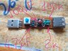
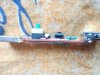
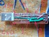
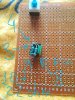
OP
solderdude
Grand Contributor
- Thread Starter
- #25
Which 555 did you use. Some equivalents can't draw enough current on it's 'sink' output.
What you can do is replace the 33 ohm with a LED + 100 ohm resistor and see if it blinks periodically.
When it does put the 33 ohm in parallel. Should still blink.
Then, after this is confirmed to work you may have to tweak the pulse width or frequency. Not all powerbanks are created equal.
What you can do is replace the 33 ohm with a LED + 100 ohm resistor and see if it blinks periodically.
When it does put the 33 ohm in parallel. Should still blink.
Then, after this is confirmed to work you may have to tweak the pulse width or frequency. Not all powerbanks are created equal.
OP
solderdude
Grand Contributor
- Thread Starter
- #27
The circuit is meant to be used in parallel to another device that doesn't draw enough current for the powerbank to detect.
It is not meant to be used without any extra load. If you want to use it for this you will have to change the pulse width so by increasing the 2k2.
It is not meant to be used without any extra load. If you want to use it for this you will have to change the pulse width so by increasing the 2k2.
Almost all the powerbanks i ever had had a "trick" to keep them on with low consumption devices, or even without anything plugged, the so called "always on mode". For instance in my current one it works pressing two times fast its only button (not disclosed in the manual) In others was pression it once for a couple of seconds... from what i read in google, they all have something like that. Hope it helps!
Love the 555 timer - so many uses for it!
OP
solderdude
Grand Contributor
- Thread Starter
- #30
Almost all the powerbanks i ever had had a "trick" to keep them on with low consumption devices, or even without anything plugged, the so called "always on mode".
Mine (Varta 57971) doesn't have this nor is it documented that it can do this.
hm, sorry cant help you with that specific one. My current one is a Poweradd Energycell 15000 and the always-on mode is set double pushing the button when the battery is on (lights start blinking differently). This is not disclosed in any manual, i found it out trying the different combinations i found in the internet for other models.
This keeps my rasp pi zero w+allo miniboss dac working for a few days, i dont even bother switching it off, until the environmental concious me takes control
As mentioned, other brands use other combinations. Example with explanation: https://voltaicsystems.com/always-on-batteries/
probably best to check before ordering
This keeps my rasp pi zero w+allo miniboss dac working for a few days, i dont even bother switching it off, until the environmental concious me takes control
As mentioned, other brands use other combinations. Example with explanation: https://voltaicsystems.com/always-on-batteries/
probably best to check before ordering
That video made just to show led blinking. Of course i tried it with load.The circuit is meant to be used in parallel to another device that doesn't draw enough current for the powerbank to detect.
It is not meant to be used without any extra load. If you want to use it for this you will have to change the pulse width so by increasing the 2k2.
OP
solderdude
Grand Contributor
- Thread Starter
- #33
That video made just to show led blinking. Of course i tried it with load.
When the powerbank still shuts off even with the intended load you need to change the duty cycle by changing the 2k2 value (higher value = high current is drawn longer = higher overall extra current draw.
Yeah, i've seen from ne555 calculator link you provided, that increasing R3 will increase duty cycle, and seen from usb-doctor that even 70mA is enough for one powerbank to stay on so I left R1 as it is and played a bit with R3 - 68KOhm seems to work at least for one of two powerbanks (PS 47KOhm is good too, but 20KOhm and below - not). That is enough for me. Thanks.When the powerbank still shuts off even with the intended load you need to change the duty cycle by changing the 2k2 value (higher value = high current is drawn longer = higher overall extra current draw.
PS Knowing all this nuances, may be it will be better to build such board tunable, with ponentiometers for R1 and R3, as it turns out that for some powerbanks the value of current drain is more important, than duty cycle, and for others it is otherwise.
Last edited:
OP
solderdude
Grand Contributor
- Thread Starter
- #35
Never designed a board for it. But indeed, best to use pots.
Similar threads


- Replies
- 48
- Views
- 13K

- Replies
- 19
- Views
- 1K

- Replies
- 3
- Views
- 2K
- Replies
- 4
- Views
- 872