The only thing linear in linear PS is that is line and load unregulated. In reality it is a primitive switcher that draws current from the mains in short spikes of very high amplitude - likely >5× Because of that measuring RMS value of voltage doesn`t make sense since current is drawn only during current spike - rest of the cycle is not important. You might have only fraction of percent drop in RMS voltage with many volts drop during narrow current pulse. You need to scope it. Transformers have to be oversized since they have larger losses on copper windings (large RMS to AVG ratio) as well as core losses because of high frequency content.

-
WANTED: Happy members who like to discuss audio and other topics related to our interest. Desire to learn and share knowledge of science required. There are many reviews of audio hardware and expert members to help answer your questions. Click here to have your audio equipment measured for free!
You are using an out of date browser. It may not display this or other websites correctly.
You should upgrade or use an alternative browser.
You should upgrade or use an alternative browser.
Power supply 'stiffness'
- Thread starter Ingenieur
- Start date
- Thread Starter
- #22
I would probably simulate that because it's much faster than working out the math but you missed a critical spec to define the problem. What's the frequency of the peak? Most big peaks are low frequency, <120Hz and subs and big systems running room correction will put out huge wattage (1Kw is not crazy) . At low frequencies and big draw the caps will drop in voltage which causes high instaneous peaks for a short period of the waveform to refill the caps. That is why you can get big current peaks far higher than the average current (obviously) but higher than most, like you, expect. A good torture test for the supply is 120Hz tones 180 degrees out of phase with the mains ... Assuming 60Hz of course.
I agree, if the amp draws power like a hair dryer you will see more Vdrop (as in the case of the 1800 W hair dryer, mostly R).
But my measurements:
My estimate is likely high.
I have a sub, that contributed to the 75 dBA. I'd be surprised if I drew 2 A (60 W peak / ch).
The Z of the ckt ~0.1
12 ft #14 ~0.035 Ohm
as far as I can tell PST8 relay 0.075 Ohm from spec sheet.
Connections: plug & PST 8 ????
Plug/receptacle ???
> 0.1 Ohm
Largest drop wall to PST <0.3 V
< 3 A - Computer/DAC
MY POINT: all this dedicated circuit, power cord, conditioner hubbub is silly.
A hair dry drawing continuous 1800 W = 4 V drop,
A typical 20 A circuit ~ 100' loop ~ 4 V (116)
The peak (instantaneous) can only exceed that if I > 20 A.
And that assumes you dip into the caps (plus PS xfmr drop).
Most rails have headroom
If AC is 120 VAC
DC ~ 2 x sqrt2 / Pi ~ 108 VDC
If rails ~ +/- 55 VDC a peak ~ sinusoidal ~ 39 V rms, into 8 ohm ~ 190 W
But most amps with that rail ~100-150 W or
49 V peak, so V drop should not effect performance much.
They key imho: large C and xfmr VA
At that point line V fluctuation is moot
- Thread Starter
- #23
The only thing linear in linear PS is that is line and load unregulated. In reality it is a primitive switcher that draws current from the mains in short spikes of very high amplitude - likely >5× Because of that measuring RMS value of voltage doesn`t make sense since current is drawn only during current spike - rest of the cycle is not important. You might have only fraction of percent drop in RMS voltage with many volts drop during narrow current pulse. You need to scope it. Transformers have to be oversized since they have larger losses on copper windings (large RMS to AVG ratio) as well as core losses because of high frequency content.
If the load is discharging the caps it is not designed properly. The real power, not reactive, comes from the line.
The C is in //, they act as a filter for rectification. The input AC I flows 360 degree, and is rectified. It's not switched nor commutated in the traditional sense.
If the caps were charging on some time constant the duty cycle would be small.
To get 100 W i(say 200 VA) ~ 1.7 A rms on 60 cycle
Z of amp = 120/1.7 ~ 70 Ohm
We know the PF is 0.9 range (leading) or lower
45 deg
R = 58 Ohm
X = 0.03 Ohm in // (60 Hz, C ~ 88,000 uF)
TC ~ 5 sec, > 1/60 sec, , the caps just 'float'
At no load basically bias current Z >1500 Ohm so TC 0.01 sec, much smaller/faster, X ~ the same
The input line I is 60 Hz sinusoidal distorted by the non-conducting region of the diodes
Attachments
audio2design
Major Contributor
- Joined
- Nov 29, 2020
- Messages
- 1,769
- Likes
- 1,830
If the load is discharging the caps it is not designed properly. The real power, not reactive, comes from the line.
The C is in //, they act as a filter for rectification. The input AC I flows 360 degree, and is rectified. It's not switched nor commutated in the traditional sense.
The input line I is 60 Hz sinusoidal distorted by the non-conducting region of the diodes
Obviously there is some fundamental lack of understanding that you have wrt how a practical linear power supply works. Time to put that MSEE down and pick up a basic book on linear power supplies. This isn't how most switched mode power supplies for audio work either.
The graph you show appears to be perhaps a choke regulated supply but that is not remotely practical at any significant amount of power draw. Remember that load reflects to the input. Because of that you end up with variable voltage on the caps vrt loading as well if you are choke regulating.
Last edited:
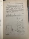
Current is drawn for charging capacitors for a moment close to peak when 120Hz half wave voltage become higher than capacitor voltage (that dropped) ending at the top of sinewave. Very low ripple will shorten these charging periods and amplitude will increase. To make it worse, at the peak diodes will get polarized in reverse but will still conduct for very short moment before switching off. This "snap back" is extremely short being able to couple to any inductance in the area. Using fast diodes with slow snap back (like Hexfreds) helps, but power supply is still polluting.
Again to see why measuring RMS of voltage doesn't make any sense put scope on resistor in series with return. You will see square narrow pulse near the peak of sinewave. The rest of the period doesn`t matter, since there is no charging current.
Again to see why measuring RMS of voltage doesn't make any sense put scope on resistor in series with return. You will see square narrow pulse near the peak of sinewave. The rest of the period doesn`t matter, since there is no charging current.
Yes, there are power supplies with constant current draw, but impractical and almost never used. One reason, that audio2design mentioned, is power loss, but also inductance would have to be in henries making chokes extremely big. In addition such supplies have lower output voltage and are sensitive to load (require min load).
- Thread Starter
- #27
Another way of looking at it, reactive power
80,000 uF, +/- 55 VDC, ignore ripple
1/2 C can provide 45 kVAr , X ~ 0.07 Ohm
It increases with freq but bass needs most of it.
The amp needs no VAr from the line, it supplies and corrects PF. But only by the VAr it doesn't consume. (It provides what the speaker L needs). If speaker phase is 45 deg and 100 VA (70 W) and 70 VAr.
Assume your home is drawing 50 A or 6000 VA (6 kVA) at 0.9 PF lag, 2600 VAr lag
the 2 x 70 = 140 VAr 'freed' up has little impact., PF improves from 0.9 to 0.91 and VA drops to 5900, ~1 A less reactive I from utility.
The amps pf is on the order of 0.5 leading
C >>> L
I'm afraid it's not me who has a misunderstanding.
If the rail voltage is not ~constant the PS is not sufficiently sized. A transformer is a choke. The magnitude of the line I will vary, not the frequency. Inflows continuously proportional to demand. V is constant.
It can't be illustrated any simpler than this.
80,000 uF, +/- 55 VDC, ignore ripple
1/2 C can provide 45 kVAr , X ~ 0.07 Ohm
It increases with freq but bass needs most of it.
The amp needs no VAr from the line, it supplies and corrects PF. But only by the VAr it doesn't consume. (It provides what the speaker L needs). If speaker phase is 45 deg and 100 VA (70 W) and 70 VAr.
Assume your home is drawing 50 A or 6000 VA (6 kVA) at 0.9 PF lag, 2600 VAr lag
the 2 x 70 = 140 VAr 'freed' up has little impact., PF improves from 0.9 to 0.91 and VA drops to 5900, ~1 A less reactive I from utility.
The amps pf is on the order of 0.5 leading
C >>> L
Obviously there is some fundamental lack of understanding that you have wrt how a practical linear power supply works. Time to put that MSEE down and pick up a basic book on linear power supplies. This isn't how most switched mode power supplies for audio work either.
The graph you show appears to be perhaps a choke regulated supply but that is not remotely practical at any significant amount of power draw. Remember that load reflects to the input. Because of that you end up with variable voltage on the caps vrt loading as well if you are choke regulating.
I'm afraid it's not me who has a misunderstanding.
If the rail voltage is not ~constant the PS is not sufficiently sized. A transformer is a choke. The magnitude of the line I will vary, not the frequency. Inflows continuously proportional to demand. V is constant.
It can't be illustrated any simpler than this.
Attachments
- Thread Starter
- #28
You are assuming the PS is operating at 100% capacity. It is not. It is oversized.Current is drawn for charging capacitors for a moment close to peak when 120Hz half wave voltage become higher than capacitor voltage (that dropped) ending at the top of sinewave. Very low ripple will shorten these charging periods and amplitude will increase. To make it worse, at the peak diodes will get polarized in reverse but will still conduct for very short moment before switching off. This "snap back" is extremely short being able to couple to any inductance in the area. Using fast diodes with slow snap back (like Hexfreds) helps, but power supply is still polluting.
Again to see why measuring RMS of voltage doesn't make any sense put scope on resistor in series with return. You will see square narrow pulse near the peak of sinewave. The rest of the period doesn`t matter, since there is no charging current.
80,000 uF +/- 55 Vdc rail ~ 480 J (8.8 C)
Ignore power factor.
A 10 W 50 Hz signal 8 Ohm. How many J? I or Q? As a % of C capacity? Per 1 cycle.
100 W signal?
<0.1 C and 0.2 J? Less than 1 %?
If the amp is putting out 100 W and drawing 200 VA (120 VAC, 1.7 A) what charging I would you expect at what frequency? And duration?
10 A for 3 mS? 50 A for 0.6 mS?
What is the time constant of a typical PS with parameters ~ above.
We know C (less xfmr L ~ 0.003 based on parameters below, Xl <<< Xc, moot)
Line R of ~ 120 VAC / 1200 A ~ 0.1 Ohm
xfmr 600 VA PU Z of xfmr <5%, X/R ~ 10 R ~ 0.11?
Total ~ 0.1 + 0.11 ~ 0.21 Ohm
tc ~ 0.017 or 60 Hz, coincidence?
It can recharge 64% in 1 tc, it will never see that in except the most extreme cases. The I will be -36% of peak.
Much less at normal operation.
It recharges at ~ the same rate depleted, no large surges of short duration, basically at line frequency.
We are discussing the power demand of the amp from a utility supply. imho This is being made overly complicated and over-thought.
Last edited:
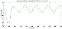
Time and current depend on amount of ripple. I would expect current at least 5x. Hard to talk about phase shift an reactive power when peak of the current is at the peak of the voltage. Picture below shows this for half wave, but for full wave will be the same.
 u
u
- Thread Starter
- #30
I doubt 5x, perhaps 2, in extreme cases when overdriven. If I get bored I may build it in Simulink/PLEX.
A short circuit fault will peak ~2.3 x steady state.
Using PS above:
Fully loaded 600/120 ~ 5 A, 240 W output
Z = 120/5 ~ 24
PF = 240/600 ~ 0.4
R ~ 10 Ohm
tc ~ 0.8 sec (likely lower since load//C)
J/sec ~ 240 or 50% of supply C
Recharge % in 1 sec, 70%
Caps 'float'
Continuous power flow
The line supplies the load power
It is not switching, it is continuous.
Line supplies rectified/filtered power.
An amp will work without caps, poorly.
Last edited:
audio2design
Major Contributor
- Joined
- Nov 29, 2020
- Messages
- 1,769
- Likes
- 1,830
Easy for a speaker to dip to 4 ohms or less in bass, let's say 20-25Hz so at the top of the waveform compared to rectified 50hz (easy math). Now looking at peak not RMS power so 500W peaks at clipping. Let's say 8msec between charge and recharge due to capacitor voltage (being kind). 15% rough derate for wave shape. joules = 0.008 * 0.85 * 500 = 3.4 joules.
55V rail = 120 joules per rail (ground referenced after all) if 80000 per rail. That's rare at that power level. 40000 would be more common (or less) so now 60 joules. 2.7V ripple on 40000uF per rail.
55V rail = 120 joules per rail (ground referenced after all) if 80000 per rail. That's rare at that power level. 40000 would be more common (or less) so now 60 joules. 2.7V ripple on 40000uF per rail.
tvrgeek
Major Contributor
The line droop is irrelevant. What matters is the amplifier rails. Is the supply stiff enough for transients?
If yo have so much money you have to look for non-existent problems, I have a bridge for sale.")
If yo have so much money you have to look for non-existent problems, I have a bridge for sale.
Picture I posted shows charging current for pretty large ripple. For very small ripple duty cycle of current will be much smaller. It will result in much higher current peaks, since the same energy has to be delivered in shorter time.
The line droop is irrelevant. What matters is the amplifier rails. Is the supply stiff enough for transients?
If yo have so much money you have to look for non-existent problems, I have a bridge for sale.
I don't begin to pretend to understand the level of the discussion the gentlemen are at.......
I do know from direct experience, a powerline droop can keep an amplifier's power supply from being able to maintain its rails.
I'm talking proaudio, high power amps...cranking subs
maybe line sag applies to some home audio amps/subs too..... beyond me.
- Thread Starter
- #35
Inductance is being ignored.
Load: speaker coil, xover
PS xfmr
the line
Assume a SC Z of 0.2 Ohm, 600 A at 120 VAC. PF ~ 0.9 lagging
Phase 26 deg
Xl = 0.087, at 60 Hz L = 230 uH
R = 0.18
PS xfmr ~ 0.03 H
1 mSec ~ <4 A
For a bolted fault
The line is NOT an ideal source and the load is not purely R. Not an infinite bus, lol.
When the line sags, rectifier V sages, it gets closer to Cv so charging time is increased, I spreads, integrated over a longer time.
- Thread Starter
- #36
Easy for a speaker to dip to 4 ohms or less in bass, let's say 20-25Hz so at the top of the waveform compared to rectified 50hz (easy math). Now looking at peak not RMS power so 500W peaks at clipping. Let's say 8msec between charge and recharge due to capacitor voltage (being kind). 15% rough derate for wave shape. joules = 0.008 * 0.85 * 500 = 3.4 joules.
55V rail = 120 joules per rail (ground referenced after all) if 80000 per rail. That's rare at that power level. 40000 would be more common (or less) so now 60 joules. 2.7V ripple on 40000uF per rail.
If you use 1/2 the C, 1 rail, it only flows 1/2 the power.
If we use 40 uF per rail ~ 60 J
Assume 100 W average 200 W peak
400 for 2 ch, 25 Hz, 16 J~ 27%
You need a tc to recover > 27% in 0.04 sec
tc = 0.11, in 0.04 sec ~ 30% recovery
tc = RC with C = 0.04 F, R = 2.75 Ohm
Typically <1 Ohm so 75% recovery.
So power flows over the C
As long as input system R < 2.75 Ohm the system should not be starved.
If a properly engineered system is operated within it's design envelope not an issue.
I know you KNOW this.
Sometimes the hunt gets the best of me.
Apologizes to those who want one, lol.
I was surprised at how low the drop was at normal operating conditions.
If if is 3 x it is still ~1 V.
audio2design
Major Contributor
- Joined
- Nov 29, 2020
- Messages
- 1,769
- Likes
- 1,830
There are a lot of mistakes in your reply and you seem unwilling to understand the fundamental operation. I calculated with reasonable accuracy the drop on the caps, 2.7V which represents 8-9V on the AC side. That's with a 500W peak albeit at 50Hz but reasonably beefy caps. Driven near limits big subs will peak 1KW+ and they tend not to have as much storage as there is enough feedback at low frequency that PSRR is not an issue. The again 40000uF per side can be in amps that do 500+W RMS short term in 4R loads so peaking 700+ which draws the caps down equivalent to 12-15V on the AC side. Standard impedance for calcs for 120V is 100uH in series with 0.4R, but if you are close to the transformer you can see much less. It's a trade off. Higher line impedance lower peak I but more drop per I. This though is how you get real world 30+ amp peaks.
No one said anything about starving. It's about what the real world voltage drops will be on the AC line.
No one said anything about starving. It's about what the real world voltage drops will be on the AC line.
Similar threads
- Poll
- Replies
- 309
- Views
- 41K
- Replies
- 136
- Views
- 27K
- Replies
- 99
- Views
- 13K