That's not going to work with halfwave rectification. Are there more diodes on the back? Schematic/circuit diagram would be nice... but this is not really the right forum for electronics talk!Magni 3+ uses a 15VAC transformer. It uses a halfwave rectifier (I see only two diodes on the board) to create +/- voltages.
Output voltages after the regulators are marked at +/- 17VDC.
My mind has gone a blank, but is there enough headroom for the regulators to work?
View attachment 286396

-
WANTED: Happy members who like to discuss audio and other topics related to our interest. Desire to learn and share knowledge of science required. There are many reviews of audio hardware and expert members to help answer your questions. Click here to have your audio equipment measured for free!
You are using an out of date browser. It may not display this or other websites correctly.
You should upgrade or use an alternative browser.
You should upgrade or use an alternative browser.
Power Supply Mod Testing for Schiit Magni 3+
- Thread starter amirm
- Start date
solderdude
Grand Contributor
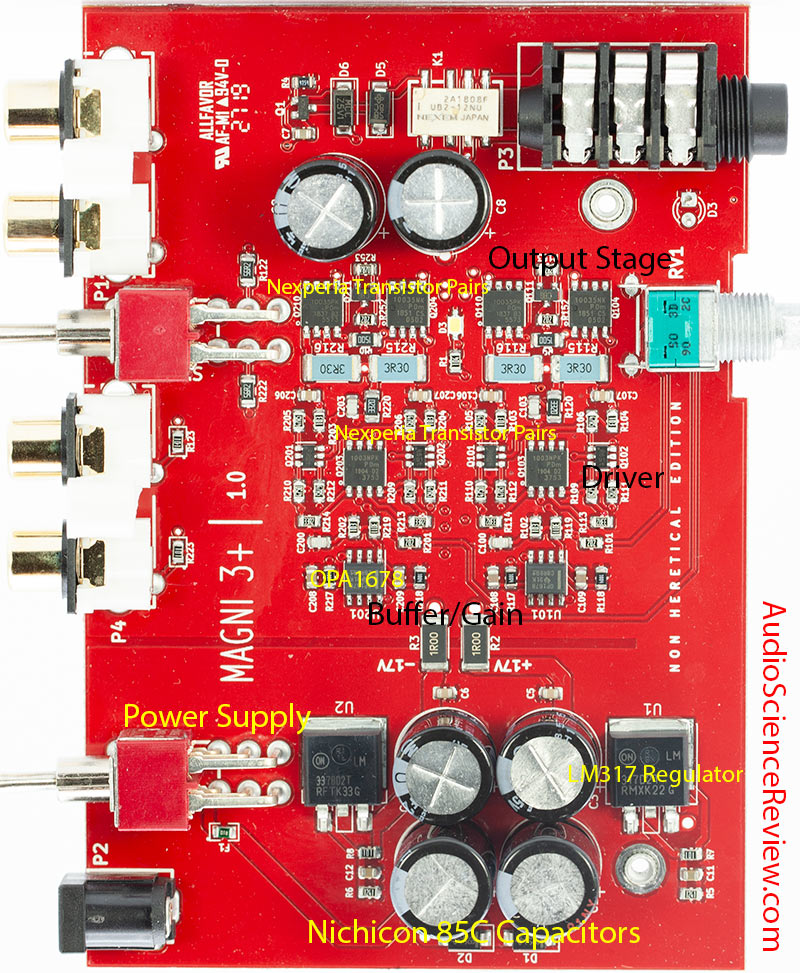
Magni 3+ uses a 15VAC transformer. It uses a halfwave rectifier (I see only two diodes on the board) to create +/- voltages.
Output voltages after the regulators are marked at +/- 17VDC.
If it isn't enough (the AC voltage on mains) there will be 50/60Hz modulation (when much power is drawn) audible.My mind has gone a blank, but is there enough headroom for the regulators to work?
A 15VAC 24VA transformer (it does not appear to be a toroid which has better regulation) then it is safe to assume 17V AC will be present and may sag to 15V under max. load.
This means there will be about +/- 22VDC (so 5V with probably 0.5V ripple) and 20VDC at full power with 1V ripple or so.
At 1A the LM317 needs 1.5V between in and out. LM337 has 2V dropout at 1A.
Of course, when the mains is unusally low in voltage the AC input on the amp will also be the same percentage lower.
Last edited:
Reiterating the warning about tantalums across supply rails. I've seen too many go up in a pink flash of smoke, despite being down rated to half their working voltage.
I agree with most of your comments, including working w these guys for... erhm... a lot of decades! ;-)Having used these devices for too many years, I never had issues with large output capacitors (1000-4700uF). If this seems a lot, imagine the devices are connected to and powering a small mixing console, with 470 uF local bypass on each rail on 24 channels, a typical application for them in the 80's. However I would never use an output capacitor of any size without the reverse bypass diode across the device. The diode prevents device failure due to reverse voltage if the input is shorted or the input rails go down quicker than the outputs on power-off. And I would never in any circumstances use a tantalum capacitor anywhere ever across a power rail if I wanted to keep my hair... (wait!) They are the most unreliable components ever made IMHO. 317/337 were convenient back in the day, but they are seriously ancient tech. Surprised they are still used. The 337 is not very good, a negative rail built with a 317 is more robust IME. Oh, and these devices are not LDO, need 3V across them to regulate...
Thoughts...
Ancient Tech, yep thats true, but hey, they work well, and they're cheap! With that bypass cap on the regulator pin, they are significantly quieter than a basic 78xx fixed reg. And, it looks like Amir proved that the changes didn't result in meaningful differences in overall noise.
I've also seen many circuits with >1000uf on the output without issues. I don't know where the modder is getting the "shouldn't have too low of an ESR on the output" idea, it doesn't seem to be in the datasheet! If you have LDO regs, now they DO have sensitivity to output cap ESR, and may oscillate if its wrong... but its usually because ESR is too high.
Measuring fast spikes, and in the <10mV range on a scope is a tricky thing, without special equip and techniques. Do you have a high speed differential probe? Did you rig up a way to minimize the ground connection to as short (few mm) as possible, or do you have the usual 4" ground lead? All the difference shown could be just how the probe and ground clip laid out on the board differently, the second time it was measured. Really, if you want to try to minimize high freq spikes, you WOULD put small value, low ESR caps across the output rail, and of course around the circuit, as they likely are.
On the diodes, well, yes its safer. But, the output, inside of a larger device like this, shouldn't ever get shorted, vs you are making a bench power supply, where there a likely chance it would. Prove to yourself your circuit won't ever look like a short and you can drop that. And if you see that you always drain output before input, you can drop the other. Id also have to say in most commercial circuits I've seen, the diodes werent implemented. Belt and suspenders, vs save costs. I would imagine Jason looked that over and deemed it safe, and went on with the another design concern... keeping the Magni at the low price point.
Jason could have put in some of the sexy, ultra low noise LDO parts that are available, had >10X less noise.... with parts that maybe cost 5-10X, and need special output caps, also 5-10X... but would you notice, in the final amp performance? (Or even be able to measure it?)
Or... use a venerable set of regulators that are cheap and good enough because of the high PSR of the rest of the circuit, and have it work pretty much as well for $20 less in final price?
I think a lot of the "picking on the designer" thinking loses track of the bigger picture, sometimes. ;-)
Last edited:
anybody with good pictures of the board? showing rectifier diodes?That's not going to work with halfwave rectification. Are there more diodes on the back? Schematic/circuit diagram would be nice... but this is not really the right forum for electronics talk!
0.8dB will not be audible if your headphone don't need that headroom, but still significant, not sure why you say that. It's more power, 0.8 dB more is that much more, let's take this reasoning further, If There is no difference between 340W and 275W Can we then say that there is also no difference between 275W and 220W? So if there is no difference between 340 and 275 and no difference between 275 and 220, can we then say that there is no difference between 340 and 220? You see where this kind of rationale can lead. 1 dB is 1 dB it is significant, very much so.In 300ohm only a 10% higher power supply rail voltage would give an increase in output voltage.
I assume the voltage determining resistors have not been changed in value or they have been changed by Schiit during production.
A 20% increase in power = 0.8dB and would not be audible.
solderdude
Grand Contributor
Exactly that... If you want an amp that goes noticeably louder than you need double, triple or quadruple the power.
1dB is not significant. Never has been, never will be.
yep, just a half wave rectifier in there. D1 and D2 (below on the board).
The input is just a regular 2 contact connector. This is just a super 'basic' power supply design.
Heresy has the same PS.
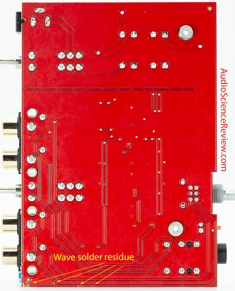
See... nothing on the bottom and power supply is just 2 contacts so one winding without center tap. Nothing mysterious about it. Just a halfwave rectifier followed by 2 standard adjustable regulators.
1dB is not significant. Never has been, never will be.
anybody with good pictures of the board? showing rectifier diodes?
yep, just a half wave rectifier in there. D1 and D2 (below on the board).
The input is just a regular 2 contact connector. This is just a super 'basic' power supply design.
Heresy has the same PS.
See... nothing on the bottom and power supply is just 2 contacts so one winding without center tap. Nothing mysterious about it. Just a halfwave rectifier followed by 2 standard adjustable regulators.
Last edited:
I personally hear it if I raise the volume by 1 dB, sorry you don't.Exactly that... If you want an amp that goes noticeably louder than you need double, triple or quadruple the power.
1dB is not significant. Never has been, never will be
solderdude
Grand Contributor
But is it significant or just barely louder ?
Would you know if an amp clips at a 0.8dB higher level ?
It is not the same as dialing the volume up 1dB.
Would you know if an amp clips at a 0.8dB higher level ?
It is not the same as dialing the volume up 1dB.
Yep. I only see half wave.Exactly that... If you want an amp that goes noticeably louder than you need double, triple or quadruple the power.
1dB is not significant. Never has been, never will be.
yep, just a half wave rectifier in there. D1 and D2 (below on the board).
The input is just a regular 2 contact connector. This is just a super 'basic' power supply design.
so how do they get a regulated +/- 17 V from just 15 V AC? leaving a couple of volts for regulation?
A proper split secondary transformer and full wave, would go further to improve this PSU.
Supercapacitors any one?
It is audible, so yes. Significant in the sense of not negligible.But is it significant ?
solderdude
Grand Contributor
Yep. I only see half wave.
so how do they get a regulated +/- 17 V from just 15 V AC? leaving a couple of volts for regulation?
A proper split secondary transformer and full wave, would go further to improve this PSU.
Supercapacitors any one?
(17VAC X 1.4) - 0.6 = 23.4V peak and assuming 0.5V ripple about 23V DC average.
The Magni's don't seem to need full-wave nor super capacitors.... obviously.
Amir's test with full power in 32ohm don't seem to show 60Hz hum components indicating the regulators are not doing their job anymore... and even if they don't there is always the PSRR of the amp itself.
Just look at most power amp designs. Even those do not need regulated power supplies or super low noise power supplies.
Last edited:
?? 15VAC not 17.(17VAC X 1.4) - 0.6 = 23.4V peak and assuming 0.5V ripple about 23V DC average.
1.4 is for full wave, isn't it?
Do they work on two wire AC?The Magni's don't seem to need full-wave nor super capacitors.... obviously.
Amir's test with full power in 32ohm don't seem to show 60Hz hum components indicating the regulators are not doing their job anymore... and even if they don't there is always the PSRR of the amp itself.
Just look at most power amp designs. Even those do not need regulated power supplies or super low noise power supplies.
An amp with greater than 100dB noise and distortion are fine, but headphone amps should be better.
BTW, I never suggested Magni Needs a PSU mod or upgrade, we are just talking about pushing the boundaries.
Just asking questions . . .
OP
- Thread Starter
- #34
Catching up, as stated, the scope pictures were that of the member who did the mod. And I fixed the title. ")
boxcarbill
New Member
- Joined
- Dec 5, 2022
- Messages
- 2
- Likes
- 2
Half wave rectifiers still output the peak voltage, just like full wave. They will only have one diode drop compared to a bridge rectifier which has 2. So the half wave will actually be ~0.6V higher, at the expense of additional ripple voltage.?? 15VAC not 17.
1.4 is for full wave, isn't it?
Do they work on two wire AC?
An amp with greater than 100dB noise and distortion are fine, but headphone amps should be better.
BTW, I never suggested Magni Needs a PSU mod or upgrade, we are just talking about pushing the boundaries.
Just asking questions . . .
15 VRMS * sqrt(2) - 0.6 ~= 20.6 VDC. After accounting for ripple this leaves about 20V.
Yes it is the same, I do not know how much peak clipping is exactly needed before it becomes audible, but I do know that when it does start to bother me, I still have 0.8 dB left that I can raise the volume level until it starts to bother me on the other amp. Some equipment here get's slammed, considered broken designs, based on some metrics that are much more theoretical in nature, and not proven audible like a 0.01% THD in their linear operation zone, basically referred as crap. 1 dB is not only significant, It is so significant that it's literally the standard measurement units in all audio signal comparisons. Would a +- 1 dB frequency response would be considered negligible variations? Would Amir's measurments be considered rigorous if everything he measures would have a plus minus half dB error?Would you know if an amp clips at a 0.8dB higher level ?
It is not the same as dialing the volume up 1dB.
Last edited:
solderdude
Grand Contributor
When an EI transformer is rated 15V AC and 24VA it is only 15V when loaded with a 24VA load.?? 15VAC not 17.
1.4 is for full wave, isn't it?
Do they work on two wire AC?
An amp with greater than 100dB noise and distortion are fine, but headphone amps should be better.
BTW, I never suggested Magni Needs a PSU mod or upgrade, we are just talking about pushing the boundaries.
Just asking questions . . .
With a much smaller load the output voltage is higher so the DC voltage is also higher. As most folks using this kind of amp will only be drawing 2W max. the transformer is virtually not loaded and the DC voltage will thus be higher and the ripple will not be too big.
When halfwave rectified you do loose some of the power so you can't draw as much power as when full-wave rectification was done.
So... the 24VA will be more like 12W or or so in practice.
The amp can deliver 2.8W in 16ohm (distorted) and with an efficiency of around 60% at full power about 9W in total is drawn so the voltage drop will still be enough to allow the LM337 (the worst one will be conducting 1A at that point and should drop at least 2V. The LM317 is dropping sightly less even.
Also, as I have no idea what diodes are used in the rectifier, there might as well be Schottky diodes in there reducing the forward voltage drop across the diode by an extra 0.2V or so.
The Magni's indeed work on 2 wire AC (so no center-tap) hence the half-wave rectifier.
There isn't much (if anything) to gain here by lowering noise or increasing the power rating of the used power supply.
Last edited:
eliash
Senior Member
- Once used such a regulator to drive an active broadband antenna design (30KHz-30MHz). I noticed considerable low frequency noise (below 120KHz) clearly audible in this frequency range with a JRC radio in regular AM mode (noise about 1-2 digit µV range). A large cap of about 1000µF at the output of the regulator lowered this noise significantly and below the radios idle noise level, probably due to its low ESR in that frequency range.
- Same thing experienced with a poor DAC power supply design, having claimed using low noise regulators to supply the audio circuit of an early ES90xy DAC chip (which has negligible noise attenuation from the audio power rails towards the audio outputs!). 3x 100µF in parallel significantly reduced the semiconductor shot noise from the regulators at low sound levels.
If it was my Shiit DAC, I would keep their design for the sake of knowing about the above!
Last edited:
A limit is imposed by data-sheet to max. output capacitance on some linear regulator. This, usually, is due to regulation compensation problem (regulator in some condition could start oscillating or generating low oscillating burst).
An attempt could be made trying to increase C1 e C2 (input capacitor) values. This can help reducing the 60 (or 50) Hz ripple. Placing in parallel to them a 1uF tantalum or MLCC capacitor can also attenuate high frequency components. Depending on layout, these HF capacitors should be placed at the input terminals or directly across the regulator input terminal and the nearby GND.
Increasing C1 and C2 should reduce input low frequency ripple. The effect depends on the DC supply source, this could limit the max. capacitor value.
If DC supply is extrenal, as it seems, could be interesting triying to supply the unit with a lab bench DC supply or a battery and verify the max. improvment you can get.
Quite right. And in this low output current application, I agree, they are fine. I don't see the original design needs mods - I'd still add the diodes thoughI think a lot of the "picking on the designer" thinking loses track of the bigger picture, sometimes. ;-)
Similar threads
- Replies
- 4
- Views
- 840
- Replies
- 3
- Views
- 313
- Poll
- Replies
- 183
- Views
- 35K
- Replies
- 2
- Views
- 920
- Replies
- 107
- Views
- 15K