• WANTED: Happy members who like to discuss audio and other topics related to our interest. Desire to learn and share knowledge of science required. There are many reviews of audio hardware and expert members to help answer your questions. Click here to have your audio equipment measured for free!

Post Directiva r1 Passive Crossovers here

ayane

Active Member
Forum Donor
Joined
Dec 15, 2018
Messages
183
Likes
687
Location
NorCal
I'm planing to build the R1 as a passive speaker at one point (I'm in the middle of moving to a new house, so wont have time for many months), but would be very interested in the results.

I find it hard to pick which crossover to build, so some real life results and measurements would be very welcome.
I'm planning to send it for measurement after I finish building crossovers, which will happen within February. Hopefully Amir can measure R1p (that's what I'm calling the passive R1 :cool:) within a few months of receiving it. It'd be amazing to have a sanity check on the predicted spin data of crossover sims in the form of Klippel verification.

Correct me if I'm wrong, but as I understand it, the choke-up in crossover design right now is the fact that the Purifi driver has changed a bit since the one used in the first active crossover build that was measured in October, and that may throw off some of these crossover designs slightly.
 

ayane

Active Member
Forum Donor
Joined
Dec 15, 2018
Messages
183
Likes
687
Location
NorCal
To me this is more logical as the phase relationship between the two drivers does not change with distance when you use the midpoint of the two voice coils. If you take one of the units (the tweeter usually) as the acoustical axis, then as you move closer or further the phase relationship changes. If you take the center of one of the units as your reference point, the phase relationship is only fully valid at that exact measurement distance. This won't matter as much in the far field of course, but I prefer the midpoint. It gives me more 'ease of mind'.
Would you mind sharing the vertical directivity heatmap sim of the crossover design you just posted? I'm curious to know how it compares to the heatmap in this sim
 

TimVG

Major Contributor
Forum Donor
Joined
Sep 16, 2019
Messages
1,193
Likes
2,643
1644004353226.png

I'd say pretty much the same.

Would you mind sharing the vertical directivity heatmap sim of the crossover design you just posted? I'm curious to know how it compares to the heatmap in this sim

Are you familiar with vcad? I can send you the project file if you want it.
 

ayane

Active Member
Forum Donor
Joined
Dec 15, 2018
Messages
183
Likes
687
Location
NorCal
Are you familiar with vcad? I can send you the project file if you want it.
That'd be great! Admittedly, I'm still learning about crossover design, but I can at least navigate vcad, haha
 

Steve Dallas

Major Contributor
Joined
May 28, 2020
Messages
1,215
Likes
2,906
Location
A Whole Other Country

kjb

Member
Joined
Feb 14, 2020
Messages
12
Likes
12
I made another version at one point, which is potentially a bit better, but I don't believe I ever posted it.
You'd have to check with Rick if the vcad simulation can be taken at face value before ordering any parts though. I wasn't involved with R1 so I don't know much of the details.

View attachment 184047
View attachment 184048
Have you tried shifting the polarity of the tweeter to see the reverse null?
I notice that the phase of the tweeter and the woofer doesn't match in the crossover region, I designed a 2 way speaker with second order electrical x-overs myself a while ago and had the same issue when simulating. I had very good directivity but the reverse null where poor, almost non existing. I decided to redesign the crossover to get better phase alignment by making the tweeter section a third order filter. The directivity suffered a bit by this making it a bit worse.
I don't now how much bad phase alignment would hurt sound quality though but many speaker designers seems to be picky with this.
 

TimVG

Major Contributor
Forum Donor
Joined
Sep 16, 2019
Messages
1,193
Likes
2,643
Have you tried shifting the polarity of the tweeter to see the reverse null?
I notice that the phase of the tweeter and the woofer doesn't match in the crossover region, I designed a 2 way speaker with second order electrical x-overs myself a while ago and had the same issue when simulating. I had very good directivity but the reverse null where poor, almost non existing. I decided to redesign the crossover to get better phase alignment by making the tweeter section a third order filter. The directivity suffered a bit by this making it a bit worse.
I don't now how much bad phase alignment would hurt sound quality though but many speaker designers seems to be picky with this.

Since there is a physical Z-axis mismatch of the voice coils due to the straight baffle, getting perfect phase matching on any particular axis becomes tricky in a passive configuration such as this. On the acoustical axis (or even the tweeter axis at a distance >1m) the drivers will blend well. Any practical issues involving phase matching will show themselves in the amplitude response, in my opinion.

Having simulated such a crossover through the miniDSP for further development of R2, and having compared a technically 'perfect' to an 'imperfect' filter, it is my opinion that the amplitude response is the dominant factor in what we hear, with the direct sound being crucial. This to the point where I wasn't sure I would be able to seperate two vastly different filters in a blind test, in my own listening room - once the direct sound of both was the same. The off axis curves were both controlled, but different.
 

BenB

Active Member
Joined
Apr 18, 2020
Messages
284
Likes
446
Location
Virginia
When there is good agreement between the phase of the tweeter and the woofer on the design axis, the result is a symmetric lobe that is centered on that axis. This makes the sound more consistent for listening positions that are a little above or below the design axis.

The vertical sonograms of TimVG's crossover show significant asymmetry near the crossover point, which is extended from about 1700 Hz all the way up to 3000 Hz, due to the shelving of the response in that band. The mainlobe extends from about 22 degrees above perpendicular to roughly 10 degrees below. Between 40 and 62 degrees below perpendicular, there is a sidelobe that has almost the same power as the mainlobe. That sidelobe may lead to improved power response estimates, because it adds off-axis dispersion where the mainlobe has narrowed significantly compared to the bands above and below the crossover shelf, but there is little consistency to the vertical dispersion.

Considering only the magnitude of the frequency response, this will cause an issue for anyone listening 10 degrees or more below perpendicular. Most designers would probably look for a greater tolerance than that, particularly for a speaker with a significant waveguide on the tweeter that causes a somewhat narrow lobe that actually IS centered on the perpendicular (at frequencies where the tweeter plays alone.)

Of course, the speaker design incorporates certain asymmetries that can't be addressed with the crossover. The tweeter and woofer have different distances to the top and bottom edge of the cabinet, for example. This will cause some asymmetry in the response regardless of phase tracking between the tweeter and woofer in the crossover region. Every design is a trade-off, and the designers make decisions about what aspects to compromise, and which to optimize. That's why it's important to view and consider all the attributes of the speaker, so we can understand the trade-offs.
 

TimVG

Major Contributor
Forum Donor
Joined
Sep 16, 2019
Messages
1,193
Likes
2,643
When there is good agreement between the phase of the tweeter and the woofer on the design axis, the result is a symmetric lobe that is centered on that axis. This makes the sound more consistent for listening positions that are a little above or below the design axis.

The vertical sonograms of TimVG's crossover show significant asymmetry near the crossover point, which is extended from about 1700 Hz all the way up to 3000 Hz, due to the shelving of the response in that band. The mainlobe extends from about 22 degrees above perpendicular to roughly 10 degrees below. Between 40 and 62 degrees below perpendicular, there is a sidelobe that has almost the same power as the mainlobe. That sidelobe may lead to improved power response estimates, because it adds off-axis dispersion where the mainlobe has narrowed significantly compared to the bands above and below the crossover shelf, but there is little consistency to the vertical dispersion.

Considering only the magnitude of the frequency response, this will cause an issue for anyone listening 10 degrees or more below perpendicular. Most designers would probably look for a greater tolerance than that, particularly for a speaker with a significant waveguide on the tweeter that causes a somewhat narrow lobe that actually IS centered on the perpendicular (at frequencies where the tweeter plays alone.)

Of course, the speaker design incorporates certain asymmetries that can't be addressed with the crossover. The tweeter and woofer have different distances to the top and bottom edge of the cabinet, for example. This will cause some asymmetry in the response regardless of phase tracking between the tweeter and woofer in the crossover region. Every design is a trade-off, and the designers make decisions about what aspects to compromise, and which to optimize. That's why it's important to view and consider all the attributes of the speaker, so we can understand the trade-offs.

You're quite right in your assessments Ben. The crossover is intended to work well midway between woofer and tweeter, up to the center of the tweeter. Like you say, every design is a trade-off, so this is a fairly simple, but effective crossover - just don't move too far below the intended listening axis. A bit of distance will give you some more leanway though, just don't lie on the floor with these.
 
OP
Rick Sykora

Rick Sykora

Major Contributor
Forum Donor
Joined
Jan 14, 2020
Messages
3,593
Likes
7,262
Location
Stow, Ohio USA
Due to some home renovation, I have been unable to complete off-axis measurements for the attached crossover. @ctrl started it I am delinquent in completing it.:facepalm:

Since some of you are evaluating potential builds, felt you should have this one even though still in a draft state. One issue this crossover attempts to address is a difference in the Purifi woofer measurements from Amir's. The speaker sent to Amir had an older woofer that measured much differently than newer ones I had acquired. I have built this crossover, and while exhibiting a little hotter highs in measurements, it sounds fine.

Enjoy!

Rick
 

Attachments

  • passive_r1.zip
    1.8 MB · Views: 116

ctrl

Major Contributor
Forum Donor
Joined
Jan 24, 2020
Messages
1,632
Likes
6,229
Location
.de, DE, DEU
How far along is this effort coming?
...
If y'all are down, please let me know which crossover to build by early next week if there's a preference, or I'll proceed with the aforementioned plan.
I'm planing to build the R1 as a passive speaker at one point (I'm in the middle of moving to a new house, so wont have time for many months), but would be very interested in the results.
Great that you want to tackle the Directiva r1 build.

To keep complications and frustration at a minimum, you (I mean no one in particular, but all DIY builders) should have the possibility to measure the loudspeaker with a calibrated measuring microphone (nowadays acquisition costs for this are low) - this of course applies to every DIY speaker build.

You should be familiar enough with the measurement software to be able to perform an indoor "gated" loudspeaker measurement.

The measurements are used to check the crossover assembly, to adjust the speaker to your listening taste and to tune the two speakers to frequency response curves that are as identical as possible. (An impedance measurement of the speaker is also often helpful for troubleshooting, but generally it should work without).

Since each driver and crossover component has certain manufacturing tolerances, deviations of +-1dB and more, when comparing two speakers, are not uncommon - which is detrimental to stereo reproduction and spatial representation.
The goal should be that the two loudspeakers do not differ more than +-0.5dB in frequency response "on average" (over a narrow frequency range it may be a little more).

If this is not the case, one of the two crossovers must be adjusted accordingly - usually it is sufficient to change a resistor in the voltage divider or something comparably simple.


Correct me if I'm wrong, but as I understand it, the choke-up in crossover design right now is the fact that the Purifi driver has changed a bit since the one used in the first active crossover build that was measured in October, and that may throw off some of these crossover designs slightly.
Exactly.

In addition, Amir was not quite sure whether the distance of the measuring microphone from the baffle was exactly the same when measuring tweeter and woofer.
This would influence the phase relation around the crossover frequency (and thus the frequency response). The excess phase of one driver would thus contain an additional phase error.

I have examined Amir's measurements again more closely and come up with a 10mm z-axis offset between tweeter and woofer (by comparing "normal" phase to minimum phase for TW and WO).
This seems plausible to me, since the measurements of @Rick Sykora and @TimVG (r2 build measurement) show similar values.
1644333849372.png
A lot of chatter from me, what I'm saying is the phase relation between TW and WO should be okay.


I have built this crossover, and while exhibiting a little hotter highs in measurements, it sounds fine.
Yes, I made a small mistake. There is about 1dB sound pressure level difference between the old Purifi driver and the new driver.
I forgot to set this accordingly in the VCAD project.

I will post a corrected VCAD project later today.

For Tim's crossover I will also post a version that simulates the frequency response with the new woofer.
 
Last edited:

KarVi71

Member
Joined
Nov 14, 2019
Messages
63
Likes
68
Great that you want to tackle the Directiva r1 build.

To keep complications and frustration at a minimum, you (I mean no one in particular, but all DIY builders) should have the possibility to measure the loudspeaker with a calibrated measuring microphone (nowadays acquisition costs for this are low) - this of course applies to every DIY speaker build.

You should be familiar enough with the measurement software to be able to perform an indoor "gated" loudspeaker measurement.

The measurements are used to check the crossover assembly, to adjust the speaker to your listening taste and to tune the two speakers to frequency response curves that are as identical as possible. (An impedance measurement of the speaker is also often helpful for troubleshooting, but generally it should work without).

Since each driver and crossover component has certain manufacturing tolerances, deviations of +-1dB and more, when comparing two speakers, are not uncommon - which is detrimental to stereo reproduction and spatial representation.
The goal should be that the two loudspeakers do not differ more than +-0.5dB in frequency response "on average" (over a narrow frequency range it may be a little more).

If this is not the case, one of the two crossovers must be adjusted accordingly - usually it is sufficient to change a resistor in the voltage divider or something comparably simple.
I have a Minidsp Umik 1, would that suffice?

I dont have much experience with measurements, so it would be new to me.

But with some guidance it should be doable.

My preamp does have Dirac Live, that should be able to correct some of the differences between speakers, but still I would like to know that they measure correct and evenly.

I have built speakers before, and also crossovers, but nothing on the level I expect from the R1.
 
OP
Rick Sykora

Rick Sykora

Major Contributor
Forum Donor
Joined
Jan 14, 2020
Messages
3,593
Likes
7,262
Location
Stow, Ohio USA
I have a Minidsp Umik 1, would that suffice?

I dont have much experience with measurements, so it would be new to me.

But with some guidance it should be doable.

My preamp does have Dirac Live, that should be able to correct some of the differences between speakers, but still I would like to know that they measure correct and evenly.

I have built speakers before, and also crossovers, but nothing on the level I expect from the R1.

Suggest this should help: https://www.audiosciencereview.com/...ning-an-active-2-way-speaker-crossover.27156/
 

Colonel7

Addicted to Fun and Learning
Joined
Feb 22, 2020
Messages
619
Likes
912
Location
Maryland, USA
For those intending to build with the passive crossovers, VituixCad can now take a modeled passive crossover and mirror it in (I believe) Equalizer APO. This way you can listen to it before ordering parts or compare a number of options, or tweak the crossover based on your actual individual driver unit measurements.
I got permission from the author @dcibel of the tutorial to post the docs based on some threads from VCad creator Kimmo at DIY Audio. Great stuff - you can see the threads @dcibel posted them on below at Midwest Audio discussion boards


Attachments

  • mirror EQ filtering.pdf
    920.4 KB · Views: 120
  • filter simulation.pdf
    415.8 KB · Views: 63

dcibel

Member
Joined
Feb 8, 2021
Messages
42
Likes
49
The mirror filter transfer function is pretty cool stuff I must admit, if a PC based active system is the goal.

For passive filters, yes you can simulate passive filters in VituixCAD and export the result directly to APO EQ as an impulse response. Not just passive filters, but any filter than can be designed in VituixCAD, so IIR and FIR included.

The caveat with simulating a passive filter transfer function, is that the simulation is the transfer function only, useful for verifying that the design is correct, fine tune that spinorama, etc. However passive filters will interact with the drivers a bit differently so non-linear effects of distortion may be present, which presents a potentially different overall sound of the APO EQ simulation and the real passive filter.

Still, rather easy to do for anyone with a multichannel soundcard, I imagine audio over HDMI to an AV receiver could work as well.

Have fun!
 

ctrl

Major Contributor
Forum Donor
Joined
Jan 24, 2020
Messages
1,632
Likes
6,229
Location
.de, DE, DEU
Sorry folks for the late post, had a lot going on and my computer is a piece of.... uhm problems.

As mentioned in other posts, @Rick Sykora had to replace the Directiva r1 woofer that Amir measured with the NFS due to a defect.

Due to the fact that the new woofer deviates significantly in frequency response, the design of a passive crossover becomes a bit tricky.

In the following I describe step by step my procedure (it is probably "description overkill", because you could describe the whole thing in one sentence).
So everyone can also use his own on-axis measurements from the SeasDXT tweeter and Purifi woofer in the speaker cabinet.

1.
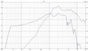
Here are the on-axis frequency responses measured by Rick. The Seas tweeter (the same driver that was measured with the NFS) and the "new" Purifi woofer measured individually in the speaker cabinet.
Both measurements were taken with the microphone position unchanged, at the height of the tweeter, @1.5m distance - @Rick Sykora correct me if I am wrong, the correct value is important.

So, the tweeter axis serves us as a reference axis (this was determined by the team, since most users use it as a guide when setting up the speakers)
1644444377202.png
Down to about 200-300Hz you can see Rick's gated in-room measurement of the "new" woofer, below that the NFS measurement of the "old" woofer has been used (to get a complete frequency response down to 20Hz).

2.
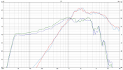
Now we overlay Rick's measurements with the old on-axis NFS measurements from SeasDXT (red) and the old Purifi woofer (green).
1644444830840.png
Ideally, the measurements of the tweeter (which was identical in Rick's and the NFS measurement) should be more or less congruent, after a sound pressure level equalization.

The deviations in the comparison of the tweeter measurements should for the most part (besides things like temperature, microphone alignment,...) be due to measurement errors and measurement tolerances of the measurement systems used.

What is clearly noticeable, however, are the considerable deviations when comparing the woofer measurements. Roughly 1dB difference in sound pressure level and in the frequency range 1-4kHz a completely different frequency response.

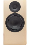
We have already speculated a lot about the possible reasons. To keep the possible sources of error as small as possible, it should be ensured that the Purifi driver has identical orientation (orientation of the surround bulges) as in the original Directiva r1 Amir measured - I think @Rick Sykora has paid attention to this.
1644481753268.png

3.
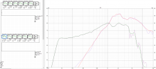
In the next step I used PEQ in VCAD to adjust the frequency responses so that they coincide (for the woofer I lowered the level by 1dB).
For the drivers, I set a smoothing of 1/6oct in VCAD to make it easier to create a match.
1644502706967.png

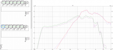
Now only the 1dB correction for the woofer has to be undone:
1644502984653.png

4.
Now the settings in VCAD should be checked in any case.

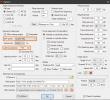
Since Rick performed his measurements at a distance of 1.5m (with tweeter axis fixed mic), the corresponding value should also be set under "Listening distance".
This optimizes the speaker for a listening distance of 1.5m, but the phase error around the crossover frequency (2.3 - 2.5 kHz) is less than 10° at 3m listening distance - so it doesn't matter much.
(when using your own measurements, check this setting first)

For the PEQ I selected the setting "miniDSP96" under "DSP system". The selection was rather random, but to prevent the frequency responses from changing, you should set the same selection.
1644504044815.png

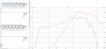
Since the tweeter has not changed, the NFS measurements should actually be okay, so I have commented out the adjustments for the SeasDXT (but everyone can handle that as they like).
1644504023481.png

So this is our VCAD project adapted to the new woofer with the NFS measurements for Directive r1.

You can find this as an attachment "corrected_NFS_0".
There you can now build your passive crossover normally.


As an example I took the crossover of Tim - see attachment "corrected_NFS_XO-Tim1".
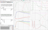
1644506106371.png

And always keep in mind that the drivers you use will also have other deviations, so it makes sense to make your own measurements to check for an optimal result after building the crossover. If the deviations are too severe, you can adjust the crossover accordingly.

Will get back to you later with some details.
 

Attachments

  • corrected_NFS_0.zip
    1.5 MB · Views: 71
  • corrected_NFS_XO-Tim1.zip
    1.5 MB · Views: 78
Last edited:
OP
Rick Sykora

Rick Sykora

Major Contributor
Forum Donor
Joined
Jan 14, 2020
Messages
3,593
Likes
7,262
Location
Stow, Ohio USA
Sorry folks for the late post, had a lot going on and my computer is a piece of.... uhm problems.

As mentioned in other posts, @Rick Sykora had to replace the Directiva r1 woofer that Amir measured with the NFS due to a defect.

Thanks @ctrl for all your efforts! If you need a computer, I have plenty. ;)

One small clarification, the Purifi woofer Amir measured was an older version and did measure differently. The matching woofer measures comparably and is operating properly. When I got the r1 speaker back from Amir, found its voice coil was rubbing. The woofer was used in a well-traveled SPK5 previously and we suspect it may have gotten damaged in shipping. It may be defective too but am not sure.
 
Last edited:

Okankav

New Member
Joined
Apr 20, 2022
Messages
3
Likes
0
Copy/paste from other thread.

Please let me preface by saying I've never actually built a passive network, and I'm sure I've made mistakes. But after getting to know Vcad a bit I came up with the following results for a passive network. If anyone who has experience with passive networks wants to take a look and correct my work.. by all means have a go.

Update after community feedback
View attachment 158325
View attachment 158328

View attachment 158324
I have a pair of ptt6.5x8nfa01 . I want to try this xover. What should I change on xover
 
Top Bottom