• WANTED: Happy members who like to discuss audio and other topics related to our interest. Desire to learn and share knowledge of science required. There are many reviews of audio hardware and expert members to help answer your questions. Click here to have your audio equipment measured for free!

Please help troubleshooting Hypex NC500MP

BklynJjm

Member
Joined
May 15, 2022
Messages
18
Likes
3
Hi all,
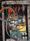
I'm at a loss to figure out what's wrong with my Hypex NC500mp build but I'm not getting any sound from it. I have a balanced input that I've verified works fine through my Crown D75 but when I swap in the NC500MP I get nothing. These units have the built in power supply and I"ve checked and rechecked the connections I've attached a picture of my test build and here is the data sheet Hypex NC500MP data sheet
I have 120v at the power input and I hear an audible click when the amp turns on. The amp generates a bit of heat when left on but isn't hot at all. Am I correct to assume that if the unit triggered one of the protection circuits it would not get hot at all? I don't measure any DC on the input but I do see -4.6v on the speaker output with no source connected. Does that indicate a problem? Any ideas where I should look next?
Thanks for the help

Jim
 
OP
B

BklynJjm

Member
Joined
May 15, 2022
Messages
18
Likes
3
Adding picture
 

Attachments

  • HYPEX NC500MP test build_small.jpg
    HYPEX NC500MP test build_small.jpg
    409.2 KB · Views: 118

chuckt62

Active Member
Editor
Joined
Apr 6, 2022
Messages
141
Likes
123
Location
Tejas
What do you measure J6.1, 2 & 4 to J6.3?

P.S.
It looks like you are forcing into standby with the jumper from GND to PS Enable.
SMPS in standby Logic Low level
Maybe not it seems to match the Ghent jumper connector. I swapped 3/4 in my head
 
Last edited:

chuckt62

Active Member
Editor
Joined
Apr 6, 2022
Messages
141
Likes
123
Location
Tejas
That's the standby Vout, should be 5V. What about 1 & 2 to 4?
 
OP
B

BklynJjm

Member
Joined
May 15, 2022
Messages
18
Likes
3
retrying on J6. without the jumper I get 5 volts between j6.3 and j6.4
 

chuckt62

Active Member
Editor
Joined
Apr 6, 2022
Messages
141
Likes
123
Location
Tejas
That's good AFAIK. I think the main supply is on J7, the single row conn. 1 & 2 to GND should be ±20VDC.
 
OP
B

BklynJjm

Member
Joined
May 15, 2022
Messages
18
Likes
3
thanks for the help. The data sheet for the J7 says its for a tweeter amp and should not be used for other purposes. The J4 is the main out
 

chuckt62

Active Member
Editor
Joined
Apr 6, 2022
Messages
141
Likes
123
Location
Tejas
That's what I was thinking, so that ±10V doesn't look great. Can you measure w/the jumper installed?
 
OP
B

BklynJjm

Member
Joined
May 15, 2022
Messages
18
Likes
3
so with the j6.3 to j6.9 connected
J6.1 to j6.3 0.5 mV
j6.2 to j6.3 = 0.6 mV
j6.4 to j6.3 = 0.8 mV
 
OP
B

BklynJjm

Member
Joined
May 15, 2022
Messages
18
Likes
3
really sorry - first measurements the amp was off
Here are the Amp on measurements
with the j6.3 to j6.9 connected
J6.1 to j6.3 -4.5V.
j6.2 to j6.3 = .5.2V
j6.4 to j6.3 = 6.1V
 
OP
B

BklynJjm

Member
Joined
May 15, 2022
Messages
18
Likes
3
typo on the - the three pins are all ~5v
Here are the Amp on measurements
with the j6.3 to j6.9 connected
J6.1 to j6.3 = 4.5V
j6.2 to j6.3 = 5.2V
j6.4 to j6.3 = 6.1V
 

chuckt62

Active Member
Editor
Joined
Apr 6, 2022
Messages
141
Likes
123
Location
Tejas
Pin4 is GND not Pin3... or you can probably use a nearby screw head. I'd guess you can just add the 6.1V J6.3 measurement to the 2 & 3 measurements and get near the same ~10V that you measured before. If you don't get the ±20V you need I'd say the SMPS is jacked.

Is that a pic of the actual amp? I thought you said it was a pic of a test build.
 
OP
B

BklynJjm

Member
Joined
May 15, 2022
Messages
18
Likes
3
Thanks. New build for me. I bought the module on ebay. This is the test case. I'll verify the 10v and then chalk it up to learning experience.
 

chuckt62

Active Member
Editor
Joined
Apr 6, 2022
Messages
141
Likes
123
Location
Tejas
Also:
"I don't measure any DC on the input but I do see -4.6v on the speaker output..."
If a DC component is present at either of the speaker outputs, the nFatal bus will be pulled down. This triggers the main SMPS to switch off and the DC Error to be activated. To reset the DC Error the module must be disconnected from mains for at least 10 minutes to allow the primary capacitors tor drain.
 
Last edited:

chuckt62

Active Member
Editor
Joined
Apr 6, 2022
Messages
141
Likes
123
Location
Tejas
Thanks. New build for me. I bought the module on ebay. This is the test case. I'll verify the 10v and then chalk it up to learning experience.
I'm planning on picking up an eBay NC122MP module, so this is relevant to my next steps.
 
Top Bottom