• WANTED: Happy members who like to discuss audio and other topics related to our interest. Desire to learn and share knowledge of science required. There are many reviews of audio hardware and expert members to help answer your questions. Click here to have your audio equipment measured for free!

Paralleling DACs

Vincent Kars

Addicted to Fun and Learning
Technical Expert
Joined
Mar 1, 2016
Messages
794
Likes
1,590
I most admit the theory about why paralleling DACs would improve the sound as described here looks a bit feeble to me. http://www.dddac.com/dddac1794_other.html

This implementation made me smile.
DDDAC1794-12-deck-op-audiorek.jpg

https://audio-creative.nl/achtergrond/een-12-deks-dddac1794-roon-dsp-en-mqa/3/
 

DonH56

Master Contributor
Technical Expert
Forum Donor
Joined
Mar 15, 2016
Messages
7,891
Likes
16,699
Location
Monument, CO
Interesting if a little unconventional a description. Parallel DAC implementations have been used a long time and do have their pros and cons. Off the cuff (sure I've forgotten a few, and of course leaving out a lot of details):

Pros:
  1. Randomizes threshold errors (especially helps with steady-state signals) to improve linearity (this includes aperture -- jitter -- errors);
  2. Depending on architecture can improve SNR since signal adds coherently and noise does not so you gain a little with each extra DAC;
  3. May increase drive level from parallel outputs (again architecture-dependent);
  4. May reduce timing/settling requirements (may reduce sampling rate for each DAC, providing more time to settle); and,
  5. May provide higher sampling rate (flip side of point (4) -- use multiple DACs to provide higher effective sampling rate).
Cons:
  1. Can be very difficult to align levels and time (clocks) to integrate the DACs -- any errors will introduce spurs at combinations of sampling and signal frequencies;
  2. Combining process can add errors (switches add distortion and glitches, passive combiners can cause gain errors, distributing a low-jitter clock to parallel DACs, can be a challenge, etc.);
  3. May not gain SNR if signals do not combine (some architectures just rotate among DACs);
  4. Increased SWaP (size, weight, and power) and cost for DACs and ancillary circuits; and,
  5. Output capacitance may be higher from combined outputs, reducing output bandwidth.
FWIFM - Don
 

FrantzM

Major Contributor
Forum Donor
Joined
Mar 12, 2016
Messages
4,376
Likes
7,870
Soon we will see established audiophile companies getting in this ...
With marketing material like those :

"
"
If DAC from our competitors with only a pair of Zeblung ESS Quadro Chip cost $15,000, you can see why ours with 40 Zebulon ESS Octo DAC is a bargain at $120,000... With our architecture all digital kinks are smoothed providing then a liquid , golden and mellifluous rendition with increased resolution since the leading edge of transients are handled by those 40 octo DAC for 320 times more accuracy !!!

Numbers game as it were ...
 

DonH56

Master Contributor
Technical Expert
Forum Donor
Joined
Mar 15, 2016
Messages
7,891
Likes
16,699
Location
Monument, CO
We should all own such "bargains"... I didn't read it closely enough to see how they get 320 times more accuracy from 40 DACs...
 
D

Deleted member 65

Guest
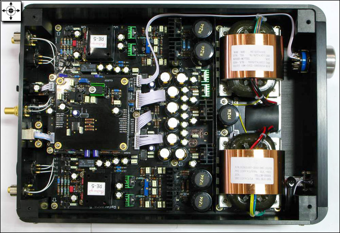
Used to have a DAC with four PCM1704 multibit chips , very well built and didn't sound bad, on the contrary. Now in my sons posession.

open3.jpg
 

amirm

Founder/Admin
Staff Member
CFO (Chief Fun Officer)
Joined
Feb 13, 2016
Messages
44,654
Likes
240,831
Location
Seattle Area

DonH56

Master Contributor
Technical Expert
Forum Donor
Joined
Mar 15, 2016
Messages
7,891
Likes
16,699
Location
Monument, CO
I had to parallel eight 1 GS/s DACs a looong time ago to achieve 8 GS/s. It was a bloody nightmare. Was not helped by the foundry substituting one of their PCM cells for my (unfortunately) identically-named bias cell -- they had no checks to prevent it, and so they had to spin the chip. They paid, thankfully, but blew my schedule.
 

Don Hills

Addicted to Fun and Learning
Joined
Mar 1, 2016
Messages
708
Likes
464
Location
Wellington, New Zealand
... This implementation made me smile. ...

It made me wince. Good idea, bad implementation. Look at the power distribution. Tiny gauge wire from the LPS, and I shudder to think how noisy the power would be by the time it got to the top DAC in the stack with the noise contributions of all the DACs below. And the ground noise back down the chain of outputs must be equally as horrendous.
 

svart-hvitt

Major Contributor
Joined
Aug 31, 2017
Messages
2,375
Likes
1,253
Parallelling, or cascading («Kaskadierung»), as Germans call it, has been the subject of many an audio forum. Take a look at this subjective review:

https://www.mutec-net.com/artikel.php?id=1388254422&lng=en

I would be happy to see measurements or theoretical explanations.

My statistical brain tells me that there may be something to dig deeper into here.

Maybe there is some randomisation going on here that has euphonic value?
 

DonH56

Master Contributor
Technical Expert
Forum Donor
Joined
Mar 15, 2016
Messages
7,891
Likes
16,699
Location
Monument, CO
See post 2... There are many, many papers with theoretical and measured results in journals of the IEEE JSSC, CAS, etc. as well as AES, IEE, and other engineering societies. I do not have a list off-hand and am disinclined to wade through them. If you have a technical background, you can get them, and if not then my hand-waving explanation plus the various web articles and posts by myself and many, many other much more qualified folk should help.
 

CuteStudio

Active Member
Joined
Nov 23, 2017
Messages
119
Likes
65
Paralleling transistors is often used for the same reasons - not for the drive (although that is obviously improved) but for noise and accuracy.
I'm not entirely sure of the maths but it sounded quite convincing at the time...
 

Thomas savage

Grand Contributor
The Watchman
Forum Donor
Joined
Feb 24, 2016
Messages
10,260
Likes
16,305
Location
uk, taunton

Frank Dernie

Master Contributor
Forum Donor
Joined
Mar 24, 2016
Messages
6,454
Likes
15,806
Location
Oxfordshire
When one considers that using relatively straightforward standard parts properly executed can produce audibly transparent results I would put this in the "unnecessary, possibly worse, bin" with boxes full of earth.
 

DonH56

Master Contributor
Technical Expert
Forum Donor
Joined
Mar 15, 2016
Messages
7,891
Likes
16,699
Location
Monument, CO
Paralleling transistors is often used for the same reasons - not for the drive (although that is obviously improved) but for noise and accuracy.
I'm not entirely sure of the maths but it sounded quite convincing at the time...

Yup, the math works, and theory and empirical results do align! With a few caveats, of course... Drive (reduced output impedance) and better thermal management are certainly reasons. Noise relative to the signal is only improved if the signal scales as well; double the signal (6 dB), and uncorrelated noise only goes up by sqrt(2) (3 dB). Matching is improved, and using certain layout tricks (cross-quads etc.) can both improve matching and reduce sensitivity to thermal and process/layout/etc. gradients. A good layout can also minimize the parasitics at the summing nodes (though they go up no matter what when you add devices, natch).

Interleaving DACs and ADCs is used to improve speed and accuracy (if implemented right) but at the cost of size, weight, power, and cost (budget). Whether or not it makes any audible difference I do not know but tend to doubt; in other applications it is required.
 

Frank Dernie

Master Contributor
Forum Donor
Joined
Mar 24, 2016
Messages
6,454
Likes
15,806
Location
Oxfordshire
Interleaving DACs and ADCs is used to improve speed and accuracy (if implemented right) but at the cost of size, weight, power, and cost (budget). Whether or not it makes any audible difference I do not know but tend to doubt; in other applications it is required.
The most amazing use of high frequency DACs I have seen is in laser doppler interferometry measuring local air speed in a wind tunnel. IIRC there were 3 4-bit converter systems looking down a laser at the light reflected back from the smoke particles in the air stream lit by the laser.
Somewhat more difficult than audio frequency stuff!
 

DonH56

Master Contributor
Technical Expert
Forum Donor
Joined
Mar 15, 2016
Messages
7,891
Likes
16,699
Location
Monument, CO
DACs, or ADCs? Much of my career focused on data converters for RADAR, LIDAR, and various EW and communications systems. There have been some very cool things, some of which I can't discuss. I have parts in the space shuttle and several jet radars plus some in wafer processing systems (to build ICs). Most of my work was in the few hundred MHz to maybe 10-40 GHz though most had to have response to DC and I have worked on systems up to 300 GHz (the latter mostly as a waveguide plumber and interested observer; I did work on some ~100 GHz radar stuff but another company took over that market for automobiles). Signal processing circuits was one of my jobs and there were some pretty cool things developed using CCDs and more conventional electronics for image processors military and civilian (mainly medical ultrasound). Audio was always a sideline and I have not done significant low-level audio design for many years though have followed along for fun.
 

svart-hvitt

Major Contributor
Joined
Aug 31, 2017
Messages
2,375
Likes
1,253
DACs, or ADCs? Much of my career focused on data converters for RADAR, LIDAR, and various EW and communications systems. There have been some very cool things, some of which I can't discuss. I have parts in the space shuttle and several jet radars plus some in wafer processing systems (to build ICs). Most of my work was in the few hundred MHz to maybe 10-40 GHz though most had to have response to DC and I have worked on systems up to 300 GHz (the latter mostly as a waveguide plumber and interested observer; I did work on some ~100 GHz radar stuff but another company took over that market for automobiles). Signal processing circuits was one of my jobs and there were some pretty cool things developed using CCDs and more conventional electronics for image processors military and civilian (mainly medical ultrasound). Audio was always a sideline and I have not done significant low-level audio design for many years though have followed along for fun.

A question out of curiosity: What’s your take on clocks? The Mutec «cascading» example I referred to above is, as far as I understand, an attempt to see what happens if you serial-connect multiple clocks.
 

DonH56

Master Contributor
Technical Expert
Forum Donor
Joined
Mar 15, 2016
Messages
7,891
Likes
16,699
Location
Monument, CO
What about them? I did not read the Mutec paper. Clocks have to be clean (low-noise, random and deterministic), preferably with fast edges (high slew) or go into good buffer stages (my designs usually used a sinusoidal clock because it was heavily filtered, then I squared it up on-chip), stable (over PVT -- process, voltage, temperature -- and time), and must arrive at the right time. In an interleaved system, if a clock edge arrives at the wrong time, it is the same as an aperture error. At the output the end result is the signal is shifted in time and the right signal at the wrong time is a wrong signal. That is why clock distribution is critical. Some chips include circuits to help align the lock edges using either a master reference (which must still be distributed properly) or on-chip delays or phase shifters to allow designers to synch up the final system. Audio systems get by easily with ps errors; some of the RF systems I worked on required fs accuracy and that was tough.

A cascade implies something different to me than an interleaved system but it may be the same thing to Mutec and others (I don't know). Time interleaving implies successively outputting from each DAC in turn so that could be considered a cascade of outputs; each output must happen at the right time or again you get sampling errors.
 
Last edited:

svart-hvitt

Major Contributor
Joined
Aug 31, 2017
Messages
2,375
Likes
1,253
What about them? I did not read the Mutec paper. Clocks have to be clean (low-noise, random and deterministic), preferably with fast edges (high slew) or go into good buffer stages (my designs usually used a sinusoidal clock because it was heavily filtered, then I squared it up on-chip), stable (over PVT -- process, voltage, temperature -- and time), and must arrive at the right time. In an interleaved system, if a clock edge arrives at the wrong time, it is the same as an aperture error. At the output the end result is the signal is shifted in time and the right signal and the wrong time is a wrong signal. That is why clock distribution is critical. Some chips include circuits to help align the lock edges using either a master reference (which must still be distributed properly) or on-chip delays or phase shifters to allow designers to synch up the final system. Audio systems get by easily with ps errors; some of the RF systems I worked on required fs accuracy and that was tough.

A cascade implies something different to me than an interleaved system but it may be the same thing to Mutec and others (I don't know). Time interleaving implies successively outputting from each DAC in turn so that could be considered a cascade of outputs; each output must happen at the right time or again you get sampling errors.

Well, the Mutec hypotheses are thus:

1) Lower phase noise is audible better.

2) Cascading of clocks has audibly benign results.

This sounds like audiophile mumble, but Mutec used to be a producer with a strong footing in no nonsense professional broadcasting circles.
 
Top Bottom