mhardy6647
Grand Contributor
- Joined
- Dec 12, 2019
- Messages
- 11,375
- Likes
- 24,600
An interesting countermelody has emerged in the Carver Crimson 275 review thread related to layout, wiring, and construction of vacuum tube audio equipment.
I thought it might be both interesting & fun to run a little bit with the topic of vintage wiring schemes, particularly point to point.
The Carver thread, e.g., shows a pretty typical consumer point to point wired product from (if I had to guess) the early 1960s.
 www.audiosciencereview.com
Pretty ugly, as the old oxymoron goes.
Another pretty ugly example of my own ken: the low-end (but popular) Pioneer SX-34/SX-34B, also sold by Allied Radio Electronics as the Knight 333. This was a late-era, all-tube AM or AM-FM stereo receiver, available until the late 1960s as a bargain priced hifi receiver. It used 6BM8 tubes (a combination triode and power pentode in one bottle) in a push-pull output configuration for about 8 wpc. It was small and very attractive... until one looked under the decks.

It is so cramped and crowded that sourcing replacement coupling capacitors that would physically fit was a bit of a challenge!
As other posts in the 'review' thread have mentioned, there were much better implemented point to point efforts.
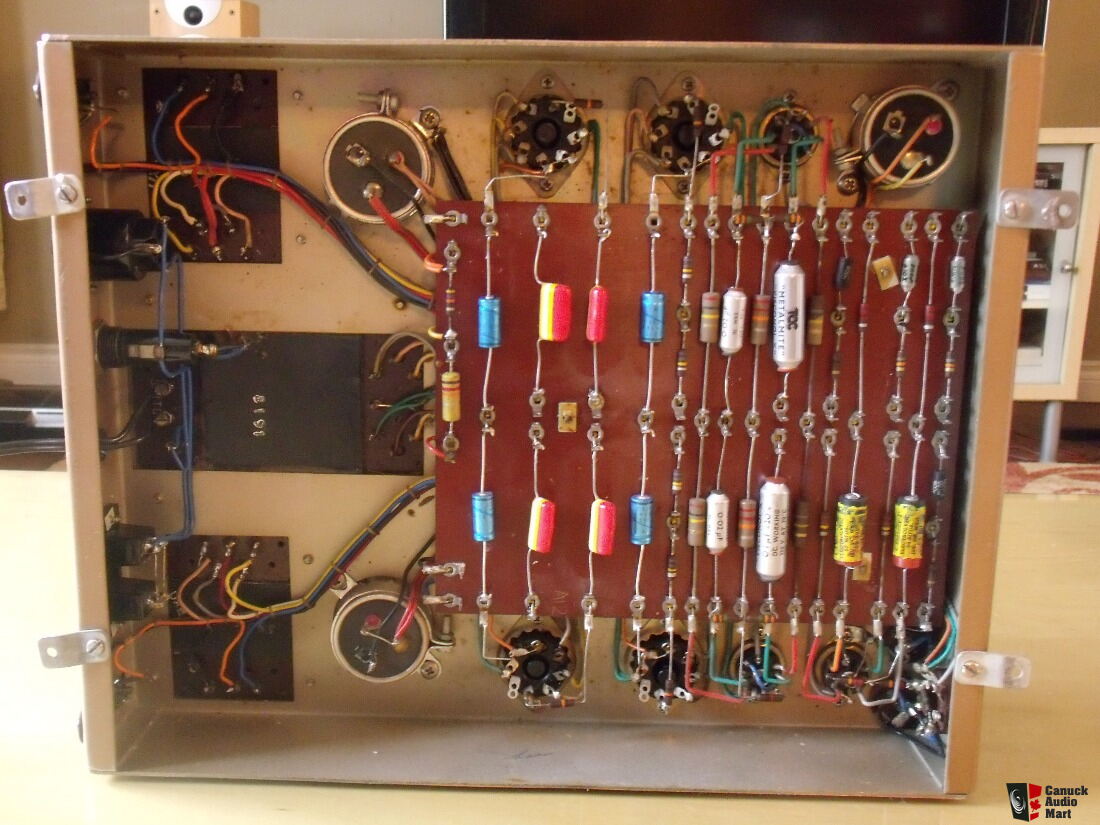
The Marantz 8B is a good example.

This is the 'before' photo of one I had the privilege to rehab some years back. Very nicely and purposefully laid out and constructed, I'd opine. A pleasure to work on and a delight to listen to -- still one of my very favorite commercially-produced vacuum tube amplifiers.
Avery Fisher's company ("The Fisher") had his group of German engineers ("The Dutchmen") who designed the classic Fisher components. To my mind, they did a nice, thoughtful, and decidedly Teutonic") job of layout in the 1960s-era Fisher stereo receivers. Not coincidentally, I enjoy rehabbing these -- they're easy to work on and sound very nice once freshened up a bit, too.
job of layout in the 1960s-era Fisher stereo receivers. Not coincidentally, I enjoy rehabbing these -- they're easy to work on and sound very nice once freshened up a bit, too.
Here's a "before" photo of a Fisher 400 receiver from the mid-'60s illustrating the clean, open, and logical layout of this entry-level (and very successful) Fisher product.

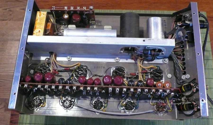
Finally, there were also manufacturers, such as McIntosh, who used turret board construction to good effect.
I haven't "done" any Mac amps so here's a borrowed photo of the innards of my own favorite Mac vacuum tube component: the venerable MC-225 stereo power amp. Not so functionally "logical" in terms of tracing out a circuit, but neat, elegant, accessible, and easy to work on. Early Mac ss componentry wasn't all that different underneath.
I guess my point -- if I have one! -- is that point to point wiring quality and design ran the gamut.
FWIW, I still like point to point for vacuum tube amplifiers -- heat was not kind to early PC board vacuum tube hardware, although modern PC board construction materials & design may be more robust. I am also not a fan of PC board mounted tube sockets, due to the stress that putting tubes into sockets (especially tight ones) puts on the board(s).
I thought it might be both interesting & fun to run a little bit with the topic of vintage wiring schemes, particularly point to point.
The Carver thread, e.g., shows a pretty typical consumer point to point wired product from (if I had to guess) the early 1960s.
Carver Crimson 275 Review (Tube Amp)
So you basically bypassed the grounding resistor used in the amplifier? This is how Carver says to measure the amp I order to not bypass that resistor. Load to speaker terminals, FFT ground to audio ground. This was addressed in the previous review I posted already. The sweeps I posted...
www.audiosciencereview.com
Pretty ugly, as the old oxymoron goes.
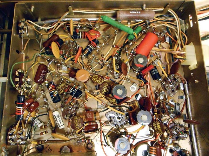
Another pretty ugly example of my own ken: the low-end (but popular) Pioneer SX-34/SX-34B, also sold by Allied Radio Electronics as the Knight 333. This was a late-era, all-tube AM or AM-FM stereo receiver, available until the late 1960s as a bargain priced hifi receiver. It used 6BM8 tubes (a combination triode and power pentode in one bottle) in a push-pull output configuration for about 8 wpc. It was small and very attractive... until one looked under the decks.
It is so cramped and crowded that sourcing replacement coupling capacitors that would physically fit was a bit of a challenge!
As other posts in the 'review' thread have mentioned, there were much better implemented point to point efforts.
The Marantz 8B is a good example.
This is the 'before' photo of one I had the privilege to rehab some years back. Very nicely and purposefully laid out and constructed, I'd opine. A pleasure to work on and a delight to listen to -- still one of my very favorite commercially-produced vacuum tube amplifiers.
Avery Fisher's company ("The Fisher") had his group of German engineers ("The Dutchmen") who designed the classic Fisher components. To my mind, they did a nice, thoughtful, and decidedly Teutonic
job of layout in the 1960s-era Fisher stereo receivers. Not coincidentally, I enjoy rehabbing these -- they're easy to work on and sound very nice once freshened up a bit, too.Here's a "before" photo of a Fisher 400 receiver from the mid-'60s illustrating the clean, open, and logical layout of this entry-level (and very successful) Fisher product.
Finally, there were also manufacturers, such as McIntosh, who used turret board construction to good effect.
I haven't "done" any Mac amps
so here's a borrowed photo of the innards of my own favorite Mac vacuum tube component: the venerable MC-225 stereo power amp. Not so functionally "logical" in terms of tracing out a circuit, but neat, elegant, accessible, and easy to work on. Early Mac ss componentry wasn't all that different underneath.
I guess my point -- if I have one! -- is that point to point wiring quality and design ran the gamut.
FWIW, I still like point to point for vacuum tube amplifiers -- heat was not kind to early PC board vacuum tube hardware, although modern PC board construction materials & design may be more robust. I am also not a fan of PC board mounted tube sockets, due to the stress that putting tubes into sockets (especially tight ones) puts on the board(s).