Yep. I'm stirring the pot a touch. Shall I go back to electrocuted guy?
Yes, please")
Thanks. Great to see you back again...

Yep. I'm stirring the pot a touch. Shall I go back to electrocuted guy?
Yes, please
Thanks. Great to see you back again...
Also to further my point about the ultrasonic output level of DACs/CD players, PMA provided a measurement of his old Technics player in another thread.
So we see here that the broadband of noise is no more than about -80dBV which is about 100uV. So we come back to my point in response to PMAs original post. Inputting 10mV or more (100 x greater), as he did to create a problem, is not representative of the real world.
I am sure you know that your assumption that the broadband noise is about -80dBV is simply incorrect. Spectral analysis "noise floor" is related to spectral density and does not directly tell the noise. The noise is calculated by integration over a defined bandwidth. E.g., if you see a spectrum of noise measured with 1nV/rt(Hz) resolution (bandwidth), which would be equal to 48kHz sampling and 48000 samples in the FFT record, and you measure -130dB noise floor, you need to add 20log(rt(20000)) dB, which makes 43dB, to calculate noise over 20kHz bandwidth. So the noise RMS over 20kHz is -87dB, not -130dB. Similarly here. Noise integrated from 50kHz to 1MHz will be definitely much higher than -80dBV, it will rather be at least of 20dB higher. Spectral plot only speaks about noise at one discrete frequency measured with the analysis bandwidth used, so it is a narrow band noise. Only spectrum peaks (lines) may be read directly, regarding their amplitude.
The point is we are only interested in the levels at specific frequencies not broad band. Specifically (with Hypex) within 20kHz the of 450KHz switching frequency. Otherwise the alleged IM will fall outside of the audio band.Pavel, if I understand this correctly, the 50kHz forcing results in a 55mV (or so) error signal, which translates to 0.2 ohms? That doesn't seem very alarming.
In your last scope plot, how do you remove the time constants of your double RC filter?
Because I ask for the product, being it instrumentation or audio, to work flawlessly in the frequency range at least one order higher (10x) than is the supposed bandwidth of the signal processed. And this is not fulfilled.
View attachment 40079
Re your question of squares, I have already explained that the step response completely describes transfer function of the linear system, because impulse response is a derivative of step response and amplitude and phase response can be calculated by Hilbert transformation of impulse response. This forum calls itself "science", right? Step response quickly shows possible issues and possible stability issues, as it does here. 20kHz amplitude spectrum shows a little.
Square and step
Step response needs to be infinitely long to describe a linear system. And impulse response usually contains more information for the same length.
Square wave is used for stability issue is not for this reason. It's because square wave contains high frequency content. You can use high frequency sine wave sweep as well.
You can measure amplitude and phase with sine sweep easily.Yes, however even short step reveals system stability and behaviour at higher frequencies. Do not forget it covers both amplitude and phase. 20 kHz spectrum plot does not reveal stability issues. Sine sweep response does not cover phase. Long unit step is needed only to show low frequency behaviour. However it is interesting as well, to show high pass filter response.
I find all this defense of narrow band 20kHz measurements as manufacturer's protection only and a part of marketing strategy. This is a must for contemporary class D technology.
What 20 kHz? My frequency response measurements go up to 200 kHz:I find all this defense of narrow band 20kHz measurements as manufacturer's protection only and a part of marketing strategy.
No. Rule of thumb doesn't do shit in front of actual relevant measurements. Filtration is external, the internal circuit can work at very high frequency as you know. Using rule of thumb every where will result in shooting yourself in the foot.
The whole thing is just two aspects:
High frequency content in music
RF interference in the environment
First one it's really small, and you only need to use test signal that mimics the spectrum energy of music signal for testing.

I find all this defense of narrow band 20kHz measurements as manufacturer's protection only and a part of marketing strategy. This is a must for contemporary class D technology.
His not talking about your measurements. But that manufacturers only cares about distortion lies in 20khz BW and output impedance under 20khz and omits rf rejection performance etc.What 20 kHz? My frequency response measurements go up to 200 kHz:
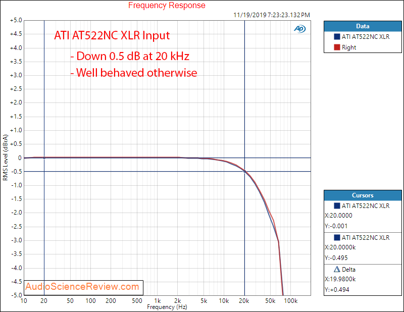
Now you get to explain what you want to do here when the amp itself has a roll off filter. What good does it do to feed it infinite bandwidth signal?