• WANTED: Happy members who like to discuss audio and other topics related to our interest. Desire to learn and share knowledge of science required. There are many reviews of audio hardware and expert members to help answer your questions. Click here to have your audio equipment measured for free!

Objective Guide to Op-Amp Rolling - Part 1

peufeu

Member
Joined
May 8, 2021
Messages
17
Likes
16
Here's an experiment that I would find interesting, so I'm suggesting it.

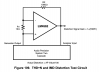
- Put opamp in unity gain buffer configuration and ground the input, so it outputs 0V.

- Connect output of opamp to output of audio source via suitable resistor, for example 1k.

- Play signal and measure distortion at the output of the opamp.

This will show the distortion added by the opamp's output stage due to load current.

You can also measure intermodulation by using two outputs from your analyzer at different frequencies, and feeding them into the opamp's output via two resistors. Or you can send one signal in the input, and one in the output via a resistor.

Since the output is a virtual ground, there is very little actual signal there, so the distortion can't hide behind it, and it is much easier to measure. Likewise, the ADC will not contribute its own distortion, since it is only acquiring the very small voltage at the output of the opamp, not the full signal amplitude. In the case of intermodulation, the ADC will see the full amplitude of one frequency but not the other, so it does not contribute its own IMD.

This will not show distortion due to other mechanisms, like input stage nonlinearity due to common mode. Only output.

Another interesting experiment is to measure distortion in the same way, with a small DC current pulled from the output of the opamp. You can vary the current, and the distortion profile will change depending on where the offset current shifts the signal on the output stage crossover of the opamp.
 

valerianf

Addicted to Fun and Learning
Joined
Dec 15, 2019
Messages
700
Likes
449
Location
Los Angeles
I remember a long time ago placing OPAxxx inside my Pioneer Laserdisc.
The sound was really improved.
But nowadays, are the OPA still on a socket on the PCB?
I do not see myself moding a 11channels AVR (I did it for 5 channels but what a pain).
 

tomchr

Addicted to Fun and Learning
Audio Company
Forum Donor
Joined
Nov 5, 2018
Messages
985
Likes
2,608
Location
Calgary, Canada
Your current measurements still only show the noise floor of your circuit and the THD+N floor of the analyzer. I.e., in the cases of the LME49720 (= LM4562) and some of the other opamps, you're not seeing the performance of the opamp. You're seeing the performance of your instrumentation.

I dug up the circuit National/TI used for the LM4562 from its data sheet. See attached. With the values shown the distortion is magnified by a factor of 101 (not 100 as it says in the figure).

Tom
 

Attachments

  • Screen Shot 2021-08-03 at 20.49.18.png
    Screen Shot 2021-08-03 at 20.49.18.png
    88.1 KB · Views: 154

syn08

Senior Member
Joined
Aug 9, 2019
Messages
376
Likes
461
Location
Toronto, Canada
I dug up the circuit National/TI used for the LM4562 from its data sheet. See attached. With the values shown the distortion is magnified by a factor of 101 (not 100 as it says in the figure).

Classic noise gain manipulation, I think Walter Jung baptized it.
 

tomchr

Addicted to Fun and Learning
Audio Company
Forum Donor
Joined
Nov 5, 2018
Messages
985
Likes
2,608
Location
Calgary, Canada
Probably. I know the guys at National didn't invent it. But if you want to show the THD of the opamp you gotta pull a few tricks.

Tom
 
OP
orchardaudio

orchardaudio

Addicted to Fun and Learning
Audio Company
Joined
Aug 24, 2018
Messages
857
Likes
1,246
Location
Succasunna, NJ
Here are results with the following added:
  • Texas Instruments NE5532
  • New Japan Radio NJM2732
  • Analog Device LT1169

Since many people requested the NE5532, I have that particular result highlighted.

This is still with a 100k load.
THD+N Ratio vs Measured Level w_ OpAmp 6dB Gain -- 100k Load -- 1kHz.jpg


SMPTE Ratio vs Measured Level -- 60Hz and 7kHz -- 22.4kHz BW -- 6dB Gain.JPG
 
  • Like
Reactions: NTK

solderdude

Grand Contributor
Joined
Jul 21, 2018
Messages
15,981
Likes
36,176
Location
The Neitherlands
The opamps themselves are loaded with 9.0k by the way.;)
 

tomchr

Addicted to Fun and Learning
Audio Company
Forum Donor
Joined
Nov 5, 2018
Messages
985
Likes
2,608
Location
Calgary, Canada
You're still just seeing the noise of the feedback resistors and the THD+N floor of the AP. For most of the opamps, the results say nothing about the opamp under test.

Tom
 

AnalogSteph

Major Contributor
Joined
Nov 6, 2018
Messages
3,370
Likes
3,311
Location
.de
I have literally never seen an NJM2742 in any audio product - at 40 nV/sqrt(Hz) of noise density and 2 MHz of GBW this hardly is the most promising part either, so no wonder. Thus the choice of this part seems puzzling. (Likewise, having both LM4562 and LME49720, which as mentioned are literally the same die.) Also, how did you operate NJM2732, a low-voltage part specified up to +6 V (presumably CMOS), from a +/-12 V supply without the magic smoke escaping?

By contrast, NJM4580s and NJM2068s are common as dirt and as such I would recommend acquiring some, even 4565s are still found occasionally (the current Focusrite Saffires are using its "reboot" version NJM8065 to drive the headphone out, it's let's say not exactly ideal for that). The NJM4556A headphone driver is another good one to try. In low-voltage circuits you also see NJM2115, as well as NJM2122 for microphone inputs (very low Vn but not remotely unity gain stable)... I think the Behringer UMC202HD actually uses both.

Note that there are actually two different LM833s out there, LM833N is the original NatSemi part while LM833P actually is TI's take on the MC33078 circuit - another type that used to be quite common at one point, btw.

Likewise, not every NE5532 is created equal... TI's seem to be among the most powerful but afflicted by rather high levels of common-mode distortion. (Study Samuel Groner's setup in this regard.)

Some of TI's OPA16xx lineup (SMD only) has become quite common - OPA1678s are increasingly seeping into audio interfaces, OPA1612s are found in high-end DACs, and I bet if you look around you'll find OPA1622s, the FET input OPA1642s and OPA1656s used as well.

Not sure what the AP software has in terms of graphing options, but I'm not even colorblind yet still find identifying the curves extremely tricky.

Low-gain distortion measurement does have merit, as there are some chips like the LM833 that seem to be using some sort of distortion compensation taking effect then, which wouldn't be active the same at high noise gain. That said, having some sort of distortion magnification setup would definitely be useful. Samuel Groner did a lot of things right, so study his methodology closely.
 
Last edited:

tomchr

Addicted to Fun and Learning
Audio Company
Forum Donor
Joined
Nov 5, 2018
Messages
985
Likes
2,608
Location
Calgary, Canada
Yeah. Especially the maroon and the sorta-brownish colours can be hard to tell apart. You can change the colours, though.

Tom
 
OP
orchardaudio

orchardaudio

Addicted to Fun and Learning
Audio Company
Joined
Aug 24, 2018
Messages
857
Likes
1,246
Location
Succasunna, NJ
Yeah. Especially the maroon and the sorta-brownish colours can be hard to tell apart. You can change the colours, though.

Tom
I have tried to me no matter what I do it just blends together too much. I can export the data to excel if somebody here want to plot it that way. I really don't have too much time to mess with this right now. I will see if I can do something better for future tests.
 

JohnYang1997

Master Contributor
Technical Expert
Audio Company
Joined
Dec 28, 2018
Messages
7,175
Likes
18,295
Location
China
I have tried to me no matter what I do it just blends together too much. I can export the data to excel if somebody here want to plot it that way. I really don't have too much time to mess with this right now. I will see if I can do something better for future tests.
-40124f46261a93ca.png

You can do like this. Insanely bright color can actually look ok in the final graph. And you can alternate high contrast colors. Also thicken some or all traces can help in some graphs too.
 

pma

Major Contributor
Joined
Feb 23, 2019
Messages
4,602
Likes
10,766
Location
Prague
Years ago (2013) I measured some not small differences between the opamps in the CCIF IMD 19+20kHz test in a circuit with gain +101x, as attached.
 

Attachments

  • opamp_ccif2_measurement_pma.pdf
    55.7 KB · Views: 206
Top Bottom