• WANTED: Happy members who like to discuss audio and other topics related to our interest. Desire to learn and share knowledge of science required. There are many reviews of audio hardware and expert members to help answer your questions. Click here to have your audio equipment measured for free!

Noob playing with MOSFETS! advice welcomed - Not directly audio related

MCH

Major Contributor
Joined
Apr 10, 2021
Messages
2,641
Likes
2,251
Hi all,

I am working on a way to get my minidsp 2x4HD to turn off when the raspberry pi to which it is connected turns off.
The minidsp is powered by a 12V DC wallwart and uses 2.5W according to minidsp specs.
Because of safety/insurance reasons, i don't want to do anything on the mains level, so i aim to add my switch to the 12V DC line between the wallwart and the minidsp. Also, i want to do it the simplest way possible, and i believe the easiest and fastest (fastest from the operational point of view) way to do it, that does not even require to write a line of code, is by using switches/relays:

To start with, I plan to use a 5V relay connected to the 5V pins of the pi (for power) and to one of the 3.3V pins for signal. When the pi turns off, the 3.3V signal will be lost and the relay will open the circuit -> the minidsp will power off. The relay i am going to use is this:


All good there (I hope). If i understand it well, electromechanical relays will not affect the voltage, the module has a optocoupler isolator and should be more capable than enough to bear this very small load and i cannot think on anything going wrong. Please tell me if i am missing something!

However, i don't like the idea of the relay being powered all the time my system is on, and the clicks, etc, and for the long term i would prefer to find a more elegant solid state solution, and there is when i stomped into mosfets. I have absolutely no idea about electronics but as a science driven person i have done my due diligence and watched all the related Great Scott youtube videos and others :D
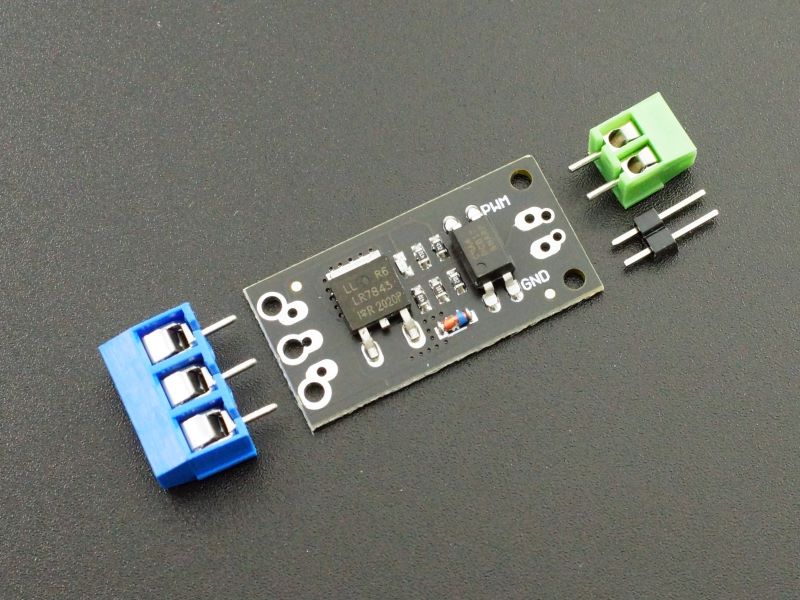
Searching Ali i came accross these modules:


In particular, the one with the LR7843 mosfet has a resistance of 3.3mOhm at 10V/15A and 4mOhm at 4.5V/12A per datasheet. I don't know how to calculate the resistance at 12V/0,2A that the minidsp will use but i am assuming it will be negligible and won't lower the voltage too much.
I plan to connect the signal to the constant 3.3V gpio pin of the pi as explained above for the relay and ground to ground, and on the other side, the 12V from the wallwart to the mosfet module, on one side and the minidsp to the other. The ground of both wallwart and minidsp go to the ground pin of the module.

As there are many knowledgeable guys here, that know about electronics and at the same time know what a minidsp processor is, i thought this would be a good place to ask for advice. The questions for you guys:
- All the info and examples i find in the internet are to power simple devices as lights and motors and stuff like that, but not complex electronics. Do you think this can work safely or am i risking blowing the minidsp?
- Any advice on how to do it better?
- Do i need any additional components in my circuit?

Thanks a lot for your help guys!
 

arvidb

Member
Joined
Dec 1, 2022
Messages
96
Likes
114
Location
Sweden
Draw a schematic (if only using pen and paper) and include the actual devices/components on the MOSFET module you found, as well as the RPi IO pin&ground and the 12VDC power&gnd and the load. That should make things clearer for you and also makes it possible for others to chime in.

In general it should work fine to switch DC power using a MOSFET. But you need to drive the gate properly (enough voltage and the "right" switching current).

I found this. Yes I think that should work fine in principle. Some electronics need a minimal rise time on the power input so maybe you should ask minidsp if that applies to your 2x4HD if you really want to make sure it'll be ok. (MOSFET switches can create very fast rise and fall times which can actually damage some sensitive electronics, or at least make them not power up properly.) Actually, looking at the schematic again it has 4.7kΩ resistors on the gate (both pull-up and pull-down) so rise and fall times should be controlled. It'll probably be just fine.
 
  • Like
Reactions: MCH
OP
M

MCH

Major Contributor
Joined
Apr 10, 2021
Messages
2,641
Likes
2,251
hi @arvidb thanks a lot for your answer and the link, very valuable indeed!
I have drawn the schematic, and only when i was finished i saw it is in your link as well!
mosfet2.jpg

The red points represent the pins of the module. I have chosen this module because the optocoupler ("octocoupler" in the drawing :D ) isolation gives me peace of mind. I have read that the optocouplers dont need much current to get activated, but could not extract that information from the datasheet. From what i read in some places, the rpi 3.3v PWR pin1 can handle up to 50mA which i believe should be enough (?).

By the way, i took the schematic from the video below, and something that confuses me is that the guy says in minute 6:00 that if you want to drive a DC motor with this module you need to add a diode in between two of the pins (???). Is this something specific for motors or would it apply to my case as well? I don't understand what the role of the diode is there...


I hear your suggestion of the slow start for the minidsp. Will try to ask in their forum, lets see if someone answer.... do you still think it might be an issue seeing the schematic?

One thing i was a bit worried about is that it seems these modules are mainly promoted to use with PWM signals, but i believe (and hope) that the pin1 3,3V PWR signal of the rpi is a continuous voltage signal. I guess this is the case and that it is not an issue with both the module and the minidsp (i guess it could be a problem with the minidsp if it was a PWM signal...)
Well, again, thanks for your time and comments, much appreciated.
 
Last edited:

arvidb

Member
Joined
Dec 1, 2022
Messages
96
Likes
114
Location
Sweden
I don't know about the RPi pin, you'd have to look that up in the data sheet. Microcontroller pins can get pretty complicated, with pin muxes you can assign different functions to a pin (normal IO, PWM etc.). Make sure you use it as a normal GPIO pin.

If the pin can supply 50 mA that should be plenty to drive an opto-coupler. R1 is 1 kΩ, and looking at the Forward Current (IF) vs. Forward Voltage (VF) diagram in the PC817 datasheet, it can be seen that when IF = 2 mA VF will be ≈ 1 V. Using Ohm's law: IF = (3.3 V [IO pin] - 1.0 V [VF])/1 kΩ ≈ 2 mA which checks out. (BTW you can see that the Current Transfer Ratio at IF = 2 mA is about 100 %, so about 2 mA will flow through the phototransistor when the opto-coupler is active. Which is not a lot when driving a power MOSFET! The switching will be very slow; I wonder how well this module would work for actual high-current PWM use.)

The diode you mention is a flyback diode, needed with inductive loads. It's not needed with the miniDSP. When inductive loads are switched off they can generate a very high negative voltage spike which needs to be prevented by dissipating the energy through the diode. If you have a speaker driver available you can test this with a 1.5V AA battery: connect the battery to the speaker leads and watch the spark when you disconnect the battery again!

No, I don't think there will be a problem with rise time. In fact I'm pretty sure there won't be. I just can't 100 % guarantee it (I didn't design the miniDSP after all ;)). I would not hesitate to use the module myself like you are planning to if I needed the functionality. Just don't blame me if the magic smoke escapes...
 
  • Like
Reactions: MCH
OP
M

MCH

Major Contributor
Joined
Apr 10, 2021
Messages
2,641
Likes
2,251
Thanks a lot for your help, now I understand much better. Tbh the datasheet of the optocoupler was like reading swedish to me ;)
Thanks as well for the explanation about the diode! The video is pretty good, but somehow the guy missed that explanation.
Actually I think I am going to order a few of these modules (0.55 shipped from china), they seem to be very well documented and could be useful for other projects.
I am ready to take the risk. Will do some measurements first with a multimeter to check that i still have 12 volts after the module and then cross fingers.

PS: while doing my research i have seen that power strips with logic triggers for Arduino and the like exist in the US, but the closest thing i found in EU is a plug with a 12V trigger. Cool for audio devices but I wish that something similar at 3.3-5 V exists here.
 

arvidb

Member
Joined
Dec 1, 2022
Messages
96
Likes
114
Location
Sweden
Thanks a lot for your help, now I understand much better. Tbh the datasheet of the optocoupler was like reading swedish to me ;)
No wonder I aced it then! ;)
Glad I could help.
 
  • Like
Reactions: MCH
OP
M

MCH

Major Contributor
Joined
Apr 10, 2021
Messages
2,641
Likes
2,251
Does it really only use 2.5W? My miniDSP Flex is always so hot.
That is what the spec says. I also find the 2x4hd runs quite warm....

Screenshot_2023-01-09-16-53-43-80_40deb401b9ffe8e1df2f1cc5ba480b12.jpg

they don't mention the conditions... mine is running Dirac, but I am not using any analog input or output, if that makes a difference.
In any case, for this project doesn't really make a difference. 2.5W means ca. 200mA and for the MOSFET module it is recommended to add a heatsink above 5A (that would be 60W!). The eq. resistance is so low (3.3 mOhm at 10V/15A) that the additional power losses are minimal, if i understand it well.
 
OP
M

MCH

Major Contributor
Joined
Apr 10, 2021
Messages
2,641
Likes
2,251
@arvidb just wanted to report back. The mosfet is up and running, working as intended and the minidsp did not complain.
Thanks for your help!
 
OP
M

MCH

Major Contributor
Joined
Apr 10, 2021
Messages
2,641
Likes
2,251
Hello,
I am in the process of modifying my system and that includes the MOSFET switch discussed in the previous posts. It has been working flawlessly this last month and a half and i want to replicate it in a new PCB i am drawing.

I plan to use the same circuit layout but i want to switch the mosfet for this one:


It is a much smaller package (SOT23 vs TO-252) and not such low resistance as the LR7843, but still quite low at ca. 18-20 mOhm:

1677174352220.png


The datasheet does not show my exact case but my circuit as is, the gate voltage is 6V and the minidsp draws ca. 0.20 mA (2.5W 12VDC):

index.php


Seeing the datasheet of the new mosfet i think i can assume a resistance of 19 (@25°C) - 26 (@100°C) mOhm depending on temperature. These values are for currents of 5-6 A, but the datasheet also indicates that below that the resistance vs current reaches a plateau, so at my 0.2A it should be roughly the same.

1677174642798.png

Now, in these worst case scenario conditions (minidsp using 2.5W/12V -> 0.2 A current), the power dissipated by the MOSFET at 100°C would be 0.0266*0.208^2 = 1.15 mW and 0,8 mW at 25°C!!
Even if the specs are wrong and the minidsp uses 5W, the mosfet still needs to dissipate only 4.6mW at 100°C
And even if i apply crazy Dirac filters and all sorts of processing and make the minidsp draw 12W, we are still at 27 mW at the MOSFET...

The truth is that this thing is tiny (1.5*3 mm!!), and i have no idea if heat dissipation is going to become a problem in this conditions (no heatsink whatsoever), but the numbers seem right to me. Has this any chance to work or am i missing something?

Comments are appreciated, thanks!!
 

fpitas

Master Contributor
Forum Donor
Joined
Jul 7, 2022
Messages
9,885
Likes
14,201
Location
Northern Virginia, USA
Looks fine to me. I run a few hundred mA through tiny MOSFETs switches all the time.
 
  • Like
Reactions: MCH

fpitas

Master Contributor
Forum Donor
Joined
Jul 7, 2022
Messages
9,885
Likes
14,201
Location
Northern Virginia, USA
They'll take a lot more current than that. Generally the limitation is the voltage drop. You designed your circuit to run on say, 5V, so you don't want the switch stealing voltage.
 
  • Like
Reactions: MCH

DVDdoug

Major Contributor
Joined
May 27, 2021
Messages
3,011
Likes
3,956
There are solid state relays. They are as easy to use a regular electro-mechanical relays (sometimes easier because they have an internal optical isolator which requires less current than a coil).

I used 7 solid state relays in a project a few years ago because didn't have any experience with MOSFETs and it just was easier to make 4-connections than to build the little circuits with MOSFETs & resistors. And the things were "packaged".

The only tricky part is that AC & DC relays are not (usually) interchangeable so make sure to get one rated for switching DC. ...AC SSRs are usually made with TRIACs, which latch-on until the next zero-crossing. With DC they won't turn-off until power is removed. And of course, DC SSRs only allow current flow in one direction.


...I've also done the opposite and built my own AC SSRs. I wanted something small with a form factor to build-into a regular power outlet box. It worked-out great... With Rev 2 of the PCB layout. :D
 
Last edited:
  • Like
Reactions: MCH

raindance

Major Contributor
Joined
Sep 25, 2019
Messages
1,040
Likes
970
The voltage drop across the MOSFET determines the heat dissipation and as long as it is turned hard on should be low.

I would do this with a solid state relay rather than a mosfet (lower parts count). Here is an example, not necessarily a recommendation: Panasonic AQY282EH
 
  • Like
Reactions: MCH
OP
M

MCH

Major Contributor
Joined
Apr 10, 2021
Messages
2,641
Likes
2,251
thanks all for your answers,

@DVDdoug and @raindance , when i started this project, the intention was to use a solid state relay (i didn't even know what a MOSFET was), but started reading precisely about the issues of using an AC solid state relay in a DC circuit... Then i came accross the little 58 cents (!!) module in post #1, that on top of the price is pretty well documented, and it works fantastic, so i became more interested in mosfets. I still get confused with AC and DC relays... (for instance, the one that @raindance posted, isn't it for AC??), so i abandoned that way...
Additionally, that particular MOSFET in post #10 is what they call a "basic part" in the company i use to print the PCB what means that they mount it almost for free ( 9cents a pop). I believe the complete circuit is less than 40 cents iirc.

@Plcamp thanks for the suggestion! however i see that it has a resistance of ca. 1 Ohm, and i prefer to keep that to the minimum so that the voltage that the minidsp sees stays as close to 12V as possible. with 1 Ohm and 0.2A (assuming the minidsp uses the 2.5W as per spec) would mean a very little 0.2V drop, but i want to be cautious as i don't really trust the 2.5W spec, just in case...... but thanks anyways!!
 

raindance

Major Contributor
Joined
Sep 25, 2019
Messages
1,040
Likes
970
My example was valid for AC or DC, but it has a 2.5 ohm on resistance. Of course, some of the wall wart power supplies output a bit on the high side voltage wise, but yup, there are tradeoffs (which is why it's just an example and not a recommendation).

The problem I found using SSRs for AC voltage, when I used to do such things for a living, was that they have a fair bit of leakage when turned off. So to make a device controlled by one of these safe, a bleeder resistor was needed to collapse the leakage, wasting energy. Obviously not an issue in your situation, but worth mentioning.
 
  • Like
Reactions: MCH

Plcamp

Addicted to Fun and Learning
Joined
Jul 6, 2020
Messages
860
Likes
1,318
Location
Ottawa
however i see that it has a resistance of ca. 1 Ohm, and i prefer to keep that to the minimum so that the voltage that the minidsp sees stays as close to 12V as possible.
There are similar devices that (instead of containing FETs at the secondary side of the optical isolation) provide gate drive for an external FET of your choosing.
 
  • Like
Reactions: MCH
OP
M

MCH

Major Contributor
Joined
Apr 10, 2021
Messages
2,641
Likes
2,251
Hello guys,
After a couple of months using the circuit discussed in this thread to power on and off my audio interfaces (minidsp 2x4HD @12VDC and motu ultralite mk5 @15VDC) with the tiny AO3400A MOSFET i am supper happy with the result. The transistor works reliably with the two devices, doesn't get hot, and neither minidsp nor motu complain about it.

see the switch at work, from my "first PCB" thread:
1686490839406.png


I have some parts left over that project and seeing how neat the switches are, i am thinking on building something new with them. that is a very simple USB in / USB out power switch controlled via WIFI, with either a raspberry pico W or a ESP32 module that i also have leftover from other projects.
The objective is:
- To turn on/off via wifi (manually or as part of an automated process) devices that are USB powered
- Needs to be as small as possible (the idea is to warp it inside a heat shrink sleeve so that it seems more like a cable with a small thicker part on it)
- Minimum costt possible -> using the leftover parts that i already have so the final cost on top of that stays ca. 5-10 eur per unit, mostly PCB fabrication cost.

Before you tell me "why don't you use a relay", i consider the regular relays quite big and the miniature relays or IC relays, well, i don't have any, and as one of the objective here is to use leftovers that i already have, I prefer to explore the MOSFET route before thinking on the relay route...

The schematic will be the same than previously discussed, here below i adapted it to this new project:

1686492066257.png


As you can see, the ground of the microcontroller and the USB are now connected. This must be the case as the microcontroller is powered 24/7 by the USB PSU. And you might ask, why are you using an optocoupler then? for two reasons: first because it is still a neat and demonstrated to work way to trigger the circuit, and second, because i plan to make the PCBs with mounting holes to mount DC sockets so that i can use the same PCB/circuit to make switches to power on/off devices that work at different DC voltage. In that case, there will be a jumper to isolate the microcontroller from the switched device.

OK, that was the intro, now my question:
As you can see in the schematic, there is a voltage divider, so for a 5VDC voltage, the voltage at the gate of the MOSFET will be ca. 2.5V.
Looking at the datasheets of both LR7843 and AO3400A, this seems to be enough to turn on the MOSFETs:
LR7843:
1686492921124.png

AO3400A:
1686492863869.png


But in the link shared in post #2 by arvidb, referring to this same circuit using LR7843, it says:

1686505677707.png

(edit: i had copied the wrong paragraph in the original post)


what are they referring to? is this a no go to use this circuit with a 5V power supply? why?

my second concern is this graph from the LR7843 datasheet:
1686493262555.png

let me see if i understand this graph. My case would be a gate to source voltage of 2.5V, that is, the lowest line. When the device that i switch on is working (it will be a raspberry pi 4b), i can imagine it could be drawing 1A or more. What does this mean, that the drain to source voltage is going to be 1 or more volt so that the voltage the device is going to see is not 5V anymore but something like 4 Volts or less? I thought that the beauty of this transistor is its extremely low resistance so that the voltage drop is negligible...
Is this what the guys in the link are referring to when they say that the power supply must be at least 6Volts?

If a 5V power supply is not going to work with this circuit, is there a way to modify the values of the resistors to make it work? (for instance modifying the voltage divider so that the voltave at the gate is higher than 2,5V)

Thanks for any comment or advice, i am a bit lost at the moment.
 
Last edited:
Top Bottom