

-
Welcome to ASR. There are many reviews of audio hardware and expert members to help answer your questions. Click here to have your audio equipment measured for free!
You are using an out of date browser. It may not display this or other websites correctly.
You should upgrade or use an alternative browser.
You should upgrade or use an alternative browser.
NEW GaN Amplifier : Dual ACM8816 GaN amplifier chips + AK4118AEQ [YJCO D816]
Yes but not for a reasonable design with low output impedance ( over the whole spectrum ) low noise and low distortion.
Output impedance issues are seen with tube amps due to output transformers or high impedance in the treble due to no post filter feedback in some class D designs . This interacts with the speakers impedance and produces frequency response variations unique to the combined amps speakers pair

I would deem this pathological design errors , with the exception of very very cheap class-D where you should be happy to get a working amplifiers at all for the money. Or inside an active design where the problem can be tackled by EQ
Michael Kohler
Member
- Joined
- Feb 20, 2026
- Messages
- 88
- Likes
- 16
I watched it. Good video. What’s especially nice is that a technical amateur like me can mostly understand it without my head getting too fried.
Coincidentally, it’s also personally pleasing for me because I use two amplifiers that don’t react at all to speaker impedance fluctuations: Sabaj A30A and SMSL VMV A2. I still remember when I bought them. There was this test of the SMSL VMV A2 here on ASR. I thought right away, this Axign Controller seems like a great thing. Back then, I didn’t fully understand it technically. Now I get it.
Michael Kohler
Member
- Joined
- Feb 20, 2026
- Messages
- 88
- Likes
- 16
Yes. That's basically it. I'll give a little more detail.
This is the usual explanation for beginners on how PWM is generated. The top figure shows the signal we want to amplify. There is also high frequency triangular wave (sawtooth will work to). The frequency of the triangular wave is usually about ≥20x our highest signal frequency.
These 2 signals are fed into a comparator. The output of the comparator is shown in the middle figure. The pulses are coded as +1 when our input signal is greater than the triangular wave, and -1 when our input signal is less than the triangular wave. That is our PWM waveform. (Another method to generate a similar, but not the same, waveform is to use the sigma-delta modulator. The waveform is more correctly known as PDM instead of PWM.) There is no sampling or numerical computations involved in generating the PWM and the process can be done using analog circuits.
The pulses can now be used to drive power switching transistors to switch voltages and currents at much higher levels, and output much higher power pulses. The frequency spectrum of this PWM is shown in the bottom figure. We have out original signal, along with a lot of other byproducts that we don't want. However, the levels of those byproducts are high only when they are at around the switching frequency or higher. Therefore we can recover our desired amplified signal by filtering out the high frequency components of this high power PWM. Typical we use a cutoff frequency of about 1/10 the triangular wave frequency for this low pass filter.
View attachment 558395
For "digital" amplifiers, the PWM or PDM waveform is synthesized in the digital domain instead of using the above method.
Phew. It's tough. But slowly it's sinking into my head. I get it! More and more.
What I'd still like to know, maybe you or someone else can explain it: Such an low-pass filter at the output of, I believe, all Class D or full digital amps, that's usually just a wire coil, right? So an analog filter, in my Understanding. But how come the frequency response of the full digital amp SMSL VMV A2 looks like in the following picture? That looks like a wall at 20,000 Hertz. How can that be?
My gut tells me this might not be an analog filter at all, but a digital one. Is my gut right?

The output low pass filter is usually an LC filter (a coil inductor plus a capacitor). It gives a 12 dB/octave attenuation. An LC filter has very little damping, and the actual damping relies on the resistance of the load (the loudspeaker) to dissipate the energy. There the lower the load resistance, the higher the energy dissipation and higher damping. That's why you usually see a higher response peak at the filter cutoff frequency for an 8 Ω load than for a 4 Ω load. This problem of load dependent frequency response can be effectively mitigated using post-filter feedback, as in the cases of Purifi, Hypex, Axign, Icepower, many of the newer TI chip based amplifiers with PFFB, etc.Phew. It's tough. But slowly it's sinking into my head. I get it! More and more.
What I'd still like to know, maybe you or someone else can explain it: Such an low-pass filter at the output of, I believe, all Class D or full digital amps, that's usually just a wire coil, right? So an analog filter, in my Understanding. But how come the frequency response of the full digital amp SMSL VMV A2 looks like in the following picture? That looks like a wall at 20,000 Hertz. How can that be?
My gut tells me this might not be an analog filter at all, but a digital one. Is my gut right?
View attachment 558429
Below is a block diagram of an Axign based amplifier. Since the Axign operates in the digital domain, all the digital signal processing rules and techniques apply. The brick wall filter is from the digital processing of the signal.
I'm going on some traveling starting today for the next few weeks. So my posting will be sporadic.
Just a note on the ADC in the picture above. It has to be very high bandwith and low latency or it will be a oscillator.
It is kind of difficult to fathom but this active controlled sub site explains it quite good. https://rmsacoustics.nl/activecontrol.html and https://rmsacoustics.nl/papers/whitepaperMFBdesign.pdf
To make this digitally corrected sub they needed a 756kHz ADC and prosessor with also really low latency. And that is to correct a subwoofer!
It is also the reason we use 10 to 100 MHz opamps after a 100k bandwith DAC.
But it is done all the time in motor control like this https://www.st.com/en/evaluation-tools/b-g431b-esc1.html#overview

wut. LOLI posted a YouTube video of it in this thread where you can hear this amplifier, even compared to a similarly expensive analog Class A/B amplifier.
Someone who thinks that this cheap YJCO D816 may actually measure well should get one drop shipped to @amirm assuming they want to test it (check first!)
Here stateside, the only trusted-vendor 48V 10A PSUs I see for under $80 delivered risk extra tariffs so if it turns out to be crap at least you get some recoverable value besides just using it for a passive sub, or in the garage...
Here stateside, the only trusted-vendor 48V 10A PSUs I see for under $80 delivered risk extra tariffs so if it turns out to be crap at least you get some recoverable value besides just using it for a passive sub, or in the garage...

YouTube video to “compare” sound of amplifiers. There is hardly more incorrect way how to do it.I posted a YouTube video of it in this thread where you can hear this amplifier, even compared to a similarly expensive analog Class A/B amplifier.
Also one more note on the ADC in that picture
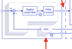
All the noise and distortion in that ADC will be fed back into the amp.
And it is a ADC with 100 to 1000 x of audiobandwith. Often they are far from comparable to an opamp input regarding noise and distortion.
Normally that would be a 12 to 14 bit ADC at 20 mhz
For motors it is 2 mhz , 12 to 14 bits and about -60 dB thd
Last edited:
And then we can ask ourselves. Is it maybe better to put a 24 bit audio bandwith DAC in front and use a 100 mhz opamp with -140 dB THD for the feedback?
Doing it digitally requires far less snalog components of cource. So that is a really nice benefit
Doing it digitally requires far less snalog components of cource. So that is a really nice benefit
Well you need to make the ADC better than the opamp. Thats quite a challenge. If the price is comparable at least
Think the trail is blazed many many years ago for a -60 dB thd digital amp.
Maybe now they have reached -80?
Think the trail is blazed many many years ago for a -60 dB thd digital amp.
Maybe now they have reached -80?
Last edited:
Michael Kohler
Member
- Joined
- Feb 20, 2026
- Messages
- 88
- Likes
- 16
I guess you don't live in Germany because you quoted the price in dollars. In Germany, the so-called original Aiyima 48 Volt 10 Ampere Gan power supply costs 59 euros including shipping. On Aliexpress. But there are also other such power supplies, not "original Aiyima," which actually cost under 40 euros, also including shipping. I was also surprised because it seemed VERY cheap to me, but in the reviews there are several buyers who measured these power supplies. According to these people, they actually have 48 volts and 10 amperes, so 480 watts.Someone who thinks that this cheap YJCO D816 may actually measure well should get one drop shipped to @amirm assuming they want to test it (check first!)
Here stateside, the only trusted-vendor 48V 10A PSUs I see for under $80 delivered risk extra tariffs so if it turns out to be crap at least you get some recoverable value besides just using it for a passive sub, or in the garage...
Michael Kohler
Member
- Joined
- Feb 20, 2026
- Messages
- 88
- Likes
- 16
Actually, I agree with you there, PMA. I would never use such a video as a benchmark when making a purchase decision, and I wouldn't advise anyone else to do so either. But 1) I don't know anything better that can be easily shared, and 2) I can say that these comparisons on the German YouTube channel 'Fidelity Hamburg,' especially regarding speakers, make sense to me. I can recognize the character of a Canton compared to a Bowers & Wilkins or an Italian Sonus Faber, because I've listened to expensive speakers from these three manufacturers extensively in real life. These models from the mentioned manufacturers have a kind of family sound, and that actually comes through in the videos. Of course, a good neutral pair of headphones is the absolute minimum requirement if someone wants to try something like that.YouTube video to “compare” sound of amplifiers. There is hardly more incorrect way how to do it.
Last edited:
Michael Kohler
Member
- Joined
- Feb 20, 2026
- Messages
- 88
- Likes
- 16
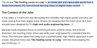
High End Audio Pearls for Electric Motor PigsI actually saw the TI video about motor control and drivers where this funny quote was made. (Hoping this ancient quote don't offend anyone anymore)
View attachment 558553
I wonder, why does an electric motor need an 'ultra low noise control'? Is that important for electric motors?
I'm happy every time you post something. My gut tells me you really know your stuff.
Unfortunately, I have to trust my gut because I only understand half of it
Guessing it is to save energy and have better control of the motor. 10 % distortion is 10% wasted energy.
+ the added heating of the motor with that power that is not transferred into movement.
I have also heard that the motor generates less sound with cleaner current.
But here I’m not an expert.
+ the added heating of the motor with that power that is not transferred into movement.
I have also heard that the motor generates less sound with cleaner current.
But here I’m not an expert.
Last edited:
Similar threads

- Replies
- 15
- Views
- 3K
- Replies
- 8
- Views
- 1K

- Replies
- 16
- Views
- 5K
