• WANTED: Happy members who like to discuss audio and other topics related to our interest. Desire to learn and share knowledge of science required. There are many reviews of audio hardware and expert members to help answer your questions. Click here to have your audio equipment measured for free!

NC252MP (class D) vs. A250W4R (classAB) burst measurements into 4ohm//2.2uF load

Fidji

Active Member
Joined
Feb 17, 2019
Messages
260
Likes
547
This is not confirmed yet, as the test was only short-term. However, in any case you get annoying whistles and 100x higher noise+distortion than with resistor. And, it is easily detectable by ear, as shown in the listening test thread. So, the warning to customers with elstat speakers similar to those listed here is IMO fair. I understand that neither manufacturers and OEM assemblers, nor fans of the amp would be happy, but let's keep emotions and business interests aside.

I think nobody in his right mind would buy cheapest available Hypex module [well second cheapest] to drive electrostats.
You go for either for HYPEX 1200 or Purifi 1ET7040SA. Quite simple solution. Tried both, both worked. Purifi had nicer box.

I had different electrostats since 20 years - they require that their owner uses the brain for both amp and positioning and acoustics. Urban legends about their requirements are highly exxagerated and usually come from people, that have no real life experience with them and just have seen some 10 old graph published.
 
OP
pma

pma

Major Contributor
Joined
Feb 23, 2019
Messages
4,602
Likes
10,768
Location
Prague
But when broken down into components, then the load the amplifier sees would be exactly that C equivalent value (or L, but that doesn't seem to be an issue) component at that exact frequency, right?
The impedance would always be composed from |Z| and φ or from R +/- jX. It seems to me, at first quick view, that you have just calculated capacitance C (Xc) without taking R into account. I may be wrong, but would need more time to check your calculations. If the impedance was pure capacitance C, the phase angle φ would have been -90°. φ = arctg(X/R).
 
D

Deleted member 48726

Guest
OP
pma

pma

Major Contributor
Joined
Feb 23, 2019
Messages
4,602
Likes
10,768
Location
Prague

I am sorry, in case of that impedance the R+C or R//C model would be an oversimplification, if we want to know what the amplifier output "sees".

The model should at least include one resonant circuit (mass, compliance, friction)
simplemodel.png

with impedance like this
simplemodelimp.png


So, it is not a capacitive load of 286uF and 5.14ohm resistor.

And

impedance.JPG


when calculating RC dummy model, we have to take into account if it is a series or parallel circuit. The formula for phase angle and modulus for parallel circuit are different then for series circuit.
 

Attachments

  • simplemodel.png
    simplemodel.png
    5.9 KB · Views: 69
  • simplemodelimp.png
    simplemodelimp.png
    22.5 KB · Views: 65
Last edited:

jimk1963

Member
Joined
Mar 20, 2023
Messages
78
Likes
107
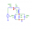
Fascinating thread for this EE. However, the author's findings raise more questions than answers. First, as has been asked multiple times, how might an individual apply this finding to his own kit? Even if one has an impedance analyzer at home, the complex impedance of, say, a 3-way speaker will be all over the place compared to the trivially simple R//C combo that was tested here. I understand the author's position that this represents perhaps an extreme load, along the lines of certain e-stats, and so is more of a cautionary tale than an outright condemnation of this particular Class D amp.

But to me, the question this report really raises is - do we need to test Class D's under a variety of complex impedance loads to better determine if there are impedance combinations that result in in-band noise (hissing, etc.)? The only real complaints I've heard/read/experienced with Class D are two-fold: (1) high frequency hissing, and (2) ear fatigue. I suspect the latter may be related to the former, but there are other factors too ("dry sounding", etc., that have been described). Anyway, keeping it scientific - we might want to look more seriously into the behavior of Class D's using either (a) dummy complex impedance loads and/or (b) connection to actual speakers (PITA, perhaps more difficult to get high-precision results I suppose).

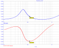
As a starting point, and I'm not an audio engineer so I don't know what's possible with test equipment - it would be informative to test this Class D amp's performance while connected to the most "problematic" e-stat speaker the ASR community is aware of.

One other comment I'll make, regarding oscillation and amplifiers. Traditional amplifiers (Class A, AB, etc.) are of course designed to have zero oscillations, either in-band or out-of-band. Oscillations in such amplifiers, even above audio range, are indicative of instability somewhere in the design. I'm an RF guy, so maybe my life has been different, but I can say with confidence that any traditional RF amp with any type of oscillation generally causes performance issues (in-band noise, IMD, etc.) and is stomped out by the designer. Most of the time it comes down to additional power supply filtering and/or careful input/output impedance matching. Class D is completely different. It's not a traditional amp at all. These amps are converting digital samples into analog waveforms, and actually require self-oscillating circuits that control sample rates. As such, and knowing that output feedback is a key element in controlling these oscillations, it should be no surprise to anyone that under varying loads - even with output feedback - we might see shifts in oscillation, and even aliasing of noise associated with the oscillation frequency(ies) back into the audio band. In the author's case, seems that's what happened - the severe capacitive load caused a shift in the amplifier's self-oscillation (or induced a secondary oscillation, i.e., subharmonic or outright additional oscillation) which folded noise back into the audio band. Any time a circuit has an unplanned/unknown resonance leading to oscillation, that nonlinear behavior almost always leads to some other consequence (noise, spurs, etc.). As others have noted, as long as it doesn't fold into the audio band, "who cares" should apply - but I would submit that any time one observes such shifting resonances, further investigation is definitely warranted. Back to the complex impedance test load thought... maybe it could help quantify these Class D audible artifacts that some have complained about. Maybe some class D's, for example, develop these in-band noise issues even with more modest complex loads. Feels like an entirely new measurement technique has potentially opened up because of this report.
 
OP
pma

pma

Major Contributor
Joined
Feb 23, 2019
Messages
4,602
Likes
10,768
Location
Prague
But to me, the question this report really raises is - do we need to test Class D's under a variety of complex impedance loads to better determine if there are impedance combinations that result in in-band noise (hissing, etc.)?
We do not need to test 100 cases of which 99 are useless to say anything. But, as a circuit designer, you know where would be the Achilles tendon, so you concentrate to that 1 in 100 options. So it goes. You need to know what you are doing. And you have to do it, rather than to spin in up and down debates.
 

jimk1963

Member
Joined
Mar 20, 2023
Messages
78
Likes
107
We do not need to test 100 cases of which 99 are useless to say anything. But, as a circuit designer, you know where would be the Achilles tendon, so you concentrate to that 1 in 100 options. So it goes. You need to know what you are doing. And you have to do it, rather than to spin in up and down debates.
Disagree it’s well known where the Achilles heel (not tendon) of these amps is, from a load perspective. If that were the case, that load would have - or should have - been standardized as a test load long ago. Looks to me like you’ve hit on something with this load test, but doesn’t mean you’ve identified the worst case load nor does this really explain how other complex loads might affect in-band noise.
 
Last edited:

jimk1963

Member
Joined
Mar 20, 2023
Messages
78
Likes
107
Erm, what?
Yeah sorry, knew that would draw a response, poorly written and forgot to change it. Obviously analog comes in, analog goes out. What I meant was, class D’s PWM implementation is a massively different architecture than a push-pull or straight class A amp. The sampling process can introduce aliased noise at low frequencies. Direct digital synthesizers, dc-dc converters, other related systems I’ve designed over the years, all are capable of really wonky frequency translations that aren’t always obvious. Reading through various class D design history, it’s not hard to envision where noise translation might occur. Found these references to be pretty helpful for example: https://sound-au.com/articles/pwm.htm

Didn’t mean to get cross-wise with the experts on here, just pointing out there is some good work in this report, and seems to me a good starting point for thinking more about best practices in testing these class D amps.
 

amirm

Founder/Admin
Staff Member
CFO (Chief Fun Officer)
Joined
Feb 13, 2016
Messages
44,590
Likes
239,533
Location
Seattle Area
NC252MP comparison of THD+N vs. power at 1kHz into 4ohm resistor load and 4ohm resistor in parallel with 2.2uF capacitor load

NC252MP_4R+2.2uF_1k_thdnlevel.png


This is the proof that the NC252MP is unusable with 4ohm//2.2uF load (simulation of the worst-case elstat. speakers)
It is not. Oscillations intermodulate with the switching frequency of the amp and create a spray that your THD+N is showing. A real speaker won't play either the oscillations or the switching frequencies so no intermodulation occurs. You can't hook up a broadband analyzer to an amp and expect at all times to get what a speaker produces.
 

amirm

Founder/Admin
Staff Member
CFO (Chief Fun Officer)
Joined
Feb 13, 2016
Messages
44,590
Likes
239,533
Location
Seattle Area
FYI I replicated this test with a couple of amplifiers. Here is the Purifi amp.

Resistive load with *no* input:
Purifi Amplifier Resistive.png


We see the switching frequency nice and sharp at around 500 kHz. Its total energy though is quite low at just 18 milliwatts. Now let's put the capacitor in parallel with it:
Purifi Amplifier Capacitive.png


We have oscillations at around 150 kHz which per my last post, is intermoduating with the switching frequency. It looks ugly but the total energy is only 72 milliwatts. In a real speaker, none of the two signals would be produced so no intermodulation occurs. In my test the analyzer basically puts no load on the amp and captures at full 1 MHz bandwidth to allow what you see.

Same test with Nilai produces this:
Nilai Amplifier 2 uF.png


Oscillation is now at 86 kHz. Total power of the ultrasonics is now at 0.9 watts but again, not anything to worry about.

To wit, the capacitor under load barely warmed to touch.

Same test with a smaller capacitor showed zero impact (I think it was 10 nf).
 

jimk1963

Member
Joined
Mar 20, 2023
Messages
78
Likes
107
With RF amps, power amps in particular, load pull tests are used to exercise the amp over a wide range of impedances to check for stability, IMD, etc. Load pull equipment can be a simple “trombone”, an adjustable length line stretcher (transmission line) with an open termination port that itself can be shorted, left open, or loaded with resistance. Adjusting the length causes a rotation of impedance around the Smith Chart, from capacitive to inductive and back again. More complex load pull equipment uses active circuitry to accomplish the same goal. I’m wondering why load pull techniques aren’t also applied to audio amps - or are they? If not, why not?
 
D

Deleted member 48726

Guest
I am sorry, in case of that impedance the R+C or R//C model would be an oversimplification, if we want to know what the amplifier output "sees".

The model should at least include one resonant circuit (mass, compliance, friction)
But my calculation is at one frequency point from a speaker impedance measurement.

What do we even use the impedance and phase measurements for if it's not to show what load the amplifier sees?

And if it IS a trace of real time impedance at various frequencies, then why can't we take an impedance at a certain frequency and break it down to show the equivalent L or C components?

I know it's not the actual electrical circuit components but the imaginary equivalent that we break down. But this surely must be as legit because it must be what the amplifier sees?

And this is a 100 % legitimate question as this is what I thought it was, a trace of impedance with an angle showing how severe an inductive (+) or capacitive (-) load the speaker is at all the frequencies.

It's true that we from this don't know if it's series or parallel. So there's that.
 

jimk1963

Member
Joined
Mar 20, 2023
Messages
78
Likes
107
FYI I replicated this test with a couple of amplifiers. Here is the Purifi amp.

Resistive load with *no* input:
View attachment 274521

We see the switching frequency nice and sharp at around 500 kHz. Its total energy though is quite low at just 18 milliwatts. Now let's put the capacitor in parallel with it:
View attachment 274523

We have oscillations at around 150 kHz which per my last post, is intermoduating with the switching frequency. It looks ugly but the total energy is only 72 milliwatts. In a real speaker, none of the two signals would be produced so no intermodulation occurs. In my test the analyzer basically puts no load on the amp and captures at full 1 MHz bandwidth to allow what you see.

Same test with Nilai produces this:
View attachment 274524

Oscillation is now at 86 kHz. Total power of the ultrasonics is now at 0.9 watts but again, not anything to worry about.

To wit, the capacitor under load barely warmed to touch.

Same test with a smaller capacitor showed zero impact (I think it was 10 nf).
Apologies if dumb question, but isn’t it possible that the load impedance presented to the amp causes the amp to generate the in-band noise and then feed that in-band noise to the speaker? Maybe I’m misunderstanding, but seems you’re saying that the speaker itself will prevent any such occurrence. Not sure I’m following.
 

amirm

Founder/Admin
Staff Member
CFO (Chief Fun Officer)
Joined
Feb 13, 2016
Messages
44,590
Likes
239,533
Location
Seattle Area
Apologies if dumb question, but isn’t it possible that the load impedance presented to the amp causes the amp to generate the in-band noise and then feed that in-band noise to the speaker? Maybe I’m misunderstanding, but seems you’re saying that the speaker itself will prevent any such occurrence. Not sure I’m following.
That's what I explained. The artifact created here is self-oscillation at high frequency. That frequency then mixes with the switching frequency of class D to create an intermodulation that the analyzer captures. A real speaker is heavily bandlimited (unlike the open load we are using here) and won't produce either tone to intermodulate down to in-band.
 

jimk1963

Member
Joined
Mar 20, 2023
Messages
78
Likes
107
That's what I explained. The artifact created here is self-oscillation at high frequency. That frequency then mixes with the switching frequency of class D to create an intermodulation that the analyzer captures. A real speaker is heavily bandlimited (unlike the open load we are using here) and won't produce either tone to intermodulate down to in-band.
But the speaker isn’t where the IMD occurs, it’s in the amplifier’s active internals, based on the load presented to it. IMD requires a nonlinearity somewhere in the system; nonlinearity comes from active circuitry, at least at signal levels below those that cause passives to generate nonlinear characteristics. So still am not following your logic that a speaker would eliminate this from happening. Separately, also not following if, or how, this disproves the in-band noise findings in this thread’s report.
 
OP
pma

pma

Major Contributor
Joined
Feb 23, 2019
Messages
4,602
Likes
10,768
Location
Prague
But my calculation is at one frequency point from a speaker impedance measurement.

What do we even use the impedance and phase measurements for if it's not to show what load the amplifier sees?

And if it IS a trace of real time impedance at various frequencies, then why can't we take an impedance at a certain frequency and break it down to show the equivalent L or C components?

I know it's not the actual electrical circuit components but the imaginary equivalent that we break down. But this surely must be as legit because it must be what the amplifier sees?

And this is a 100 % legitimate question as this is what I thought it was, a trace of impedance with an angle showing how severe an inductive (+) or capacitive (-) load the speaker is at all the frequencies.

It's true that we from this don't know if it's series or parallel. So there's that.

Your view is basically OK. Now let me explain how we check SOA (safe operating area) of power transistors used in class AB power amplifiers. I will stick with my A250W4R and your speaker load impedance that you have shown here. Quite a good approximation of its complex impedance at 120Hz is this circuit:

simplemodel.png

Impedance plot was shown here.

Now, the A250W amp uses 2 output pairs of MJL3281/1302 per channel. We need to investigate collector current Ic as a function of collector-emitter Vce voltage per 1 transistor, when the amp is driven to its maximum output and the test frequency is 120Hz (-50° phase angle).

We get plots like this:

1. with complex load shown in this image:

A250R4R_SOA1.png


The straight lines show the maximum allowed Ic as a function of Vce. The trajectory of the Ic as a function of Vce with the load used, for each transistor, can be seen as an oval shape below the straight lines boundary. This trajectory must lay below the straight lines boundary - this is a necessary condition of safe transistor operation. We can see that it is fulfilled.


2. Load is a series combination of 4ohm + 200uF

A250R4R_SOA2.png


This case is more severe, however still acceptable.


3. Load is only resistive, 4ohm resistor

A250R4R_SOA3.png


This is the easiest load and the SOA trajectory does not depend on frequency.
 
OP
pma

pma

Major Contributor
Joined
Feb 23, 2019
Messages
4,602
Likes
10,768
Location
Prague
FYI I replicated this test with a couple of amplifiers. Here is the Purifi amp.

Thank you for replicating the test. Nilai is doing better in your test, and Purifi has similar garbage above 10kHz as NC252MP, though the maximum amplitude is at 100kHz (as seen in your spectrum) and with NC252MP it is at 66kHz.

NC252MP_4R+2.2uF_HFnoise.png


With NC252MP, we have 310.6mW at 65.5kHz and 86uW at 21kHz. The total noise in 22Hz-22kHz band is however 20.22mV, and this is too much. It makes S/N at 5W (used here at ASR) 46.9dB, comparable to old tape recorders. A-weighted noise is better, 6.397mV, still only 56.9dB S/N re 5W.

So, as a conclusion, Purifi behaves similarly in this test as NC252MP, maybe a bit better, maybe not. Nilai behaves definitely much better and should not have any problems with difficult load of some electrostatic speakers.
 
Last edited:

MaxwellsEq

Major Contributor
Joined
Aug 18, 2020
Messages
1,702
Likes
2,548
That's what I explained. The artifact created here is self-oscillation at high frequency. That frequency then mixes with the switching frequency of class D to create an intermodulation that the analyzer captures. A real speaker is heavily bandlimited (unlike the open load we are using here) and won't produce either tone to intermodulate down to in-band.
I don't think that is what is happening here. Just because a speaker can't play, and indeed attenuates, above, say, 25kHz, that doesn't mean it represents no problem to an amplifier at, say, 150kHz. A power amp has no way of knowing that it's driving a loudspeaker - it simply sees a load. What this seems to show is that we need to understand the load's characteristics and the impact on the device between, say 24kHz and its switching frequency. Because this has never been an interesting problem, I don't think there is much data about loudspeaker impedance behaviour above 24kHz. I'm not confident I can say that there is no a problem, because I've not measured it and I don't think anybody else has.

Whether this behaviour is audible in double blind testing, could be gold standard for how much we care. As an engineer that's worked in both the audio band and above, I don't like to see amplifiers behave this way; perhaps we will all have to get used to it. But there's a risk that subjectivist-only audiophiles can use this as a stick to beat objectivists-first people. Which is why we either need to repeatedly prove this is "just a behaviour", but not important, or alternatively to be able to categorically state that "Class D amps are brilliant, but don't use them with the following speakers... "

I personally don't see these results as some terrible flaw that limits Class D suitability, but an opportunity to understand what are relevant, reproducible tests for power amplifiers. More work is needed to exactly define what the corner cases are. This is a start.
 
OP
pma

pma

Major Contributor
Joined
Feb 23, 2019
Messages
4,602
Likes
10,768
Location
Prague
I personally don't see these results as some terrible flaw that limits Class D suitability, but an opportunity to understand what are relevant, reproducible tests for power amplifiers. More work is needed to exactly define what the corner cases are. This is a start
I agree, but I see quite a big issue what I described just above your post. Regardless the uW peaks in audioband, which may seem low level (but let’s not forget that power uses voltage squared so mV reflects in uW), the noise flat across 22Hz-22kHz was 22mV and 6mV A weighted, and these are very, very high levels of noise voltage in audio band.
 
Top Bottom