• WANTED: Happy members who like to discuss audio and other topics related to our interest. Desire to learn and share knowledge of science required. There are many reviews of audio hardware and expert members to help answer your questions. Click here to have your audio equipment measured for free!

Minimum phase vs Mixed phase crossover in-room measurements

ppataki

Major Contributor
Joined
Aug 7, 2019
Messages
1,241
Likes
1,385
Location
Budapest
I thought I would post these measurements in case anybody is thinking about a similar design
12" fullrange drivers (2x) with 12" sub (2x) crossed over at 80Hz with 24dB/octave slope
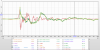
All measurements at listening position with Dirac
Scenario 1: crossover using Acon EQ mixed phase mode - blue
Scenario 2: crossover using Equilibrium Full-Minimum Phase with impulse length = 131072 - green

Frequency response 1/12 octave


1626880281001.png


Not much of a difference

Step response

1626880405496.png


Totally different ballgame....there is a slight pre-ringing with the mixed phase crossover but I cannot hear it by ear - post-ringing seems much better with the mixed phase EQ (at least in my opinion)

Spectrogram Acon
1626880604183.png


Spectrogram Equilibrium
1626880693103.png


I believe we see the same here, post ringing is pretty ugly with the minimum phase EQ and the peak energy time is also skewed

Waterfall Acon
1626880825138.png


Waterfall Equilibrium
1626880885945.png


I wonder if the larger ringing at around 50Hz and around 20Hz are caused by the additional post-ringing of the minimum phase crossover?

I tried other minimum phase EQs too and the results were very similar; also tried linear phase EQ crossover but the pre-ringing was noticeable (even when setting the impulse length pretty high)

By listening to it I prefer the sound of the mixed phase EQ to minimum phase EQ

Anyway, I hope I could contribute! :)
 

ElNino

Addicted to Fun and Learning
Joined
Sep 26, 2019
Messages
557
Likes
724
Thanks for posting! This is pretty much what you'd generally expect. If you're running at 44.1kHz, you'll probably notice slightly better imaging with the mixed phase crossover as well, because of the greater phase rotation towards 20kHz with the minimum phase crossover.
 

Frgirard

Major Contributor
Joined
Apr 2, 2021
Messages
1,737
Likes
1,042
Out of scope but the frequency response measurement - if is at listening position - is the worst measurement i saw.
The flat response is in a anechoic condition. I'm surprised dirac doesn't correct the speakers after the bass frequencies.
 

dasdoing

Major Contributor
Joined
May 20, 2020
Messages
4,288
Likes
2,759
Location
Salvador-Bahia-Brasil
Out of scope but the frequency response measurement - if is at listening position - is the worst measurement i saw.
The flat response is in a anechoic condition. I'm surprised dirac doesn't correct the speakers after the bass frequencies.

judging by the waterfall his room is treated. the dryer the room the more anechoic it becomes
 

ernestcarl

Major Contributor
Joined
Sep 4, 2019
Messages
3,110
Likes
2,327
Location
Canada
@ppataki

If I understand correctly, your mixed phase mode uses equalization that contains linear phase and minimum phase filters? But then Dirac also adds its own EQ and FIR correction to the summed response thereafter?
 
OP
P

ppataki

Major Contributor
Joined
Aug 7, 2019
Messages
1,241
Likes
1,385
Location
Budapest
@ppataki

If I understand correctly, your mixed phase mode uses equalization that contains linear phase and minimum phase filters? But then Dirac also adds its own EQ and FIR correction to the summed response thereafter?

The crossover is mixed phase. It is just one filter (Acon), not like using linear and minimum phase combined
Then comes Dirac
 

ernestcarl

Major Contributor
Joined
Sep 4, 2019
Messages
3,110
Likes
2,327
Location
Canada
The crossover is mixed phase. It is just one filter (Acon), not like using linear and minimum phase combined

The meaning of "mixed phase" has always somewhat confused me so I had to look up what Acon is and on their webpage is says:

mixed phase mode that allows you to set the latency freely in the range 5 to 120 milliseconds while preserving the phase relationships as far as possible. That gives a unique control over potential pre-ringing artifacts which is a common problem with linear phase filtering. Latency values below 20 milliseconds ensure that any pre-ringing is masked by the temporal masking of the human hearing while preserving the time-alignment across the audible frequency range.

Okay, so I think I get it... It's just the crossover filter(s) used for the sub and mains where the software automatically adjusts each driver's phase along with the crossover slope of the magnitude response -- following your set latency value. The lower the latency, (apparently) the less likely you are to hear any pre-ringing. So how many milliseconds did you set it for?

Also, I suppose this means you then let Dirac handle the remaining room/speaker EQ?
 
OP
P

ppataki

Major Contributor
Joined
Aug 7, 2019
Messages
1,241
Likes
1,385
Location
Budapest
Yes, correct
You need to use 5ms which is the lowest
Then you will have negligible pre-ringing as you can see in my measurement
Dirac handles everything else
So far for me this has been the best setup (tried looots of different plugins)
 

ernestcarl

Major Contributor
Joined
Sep 4, 2019
Messages
3,110
Likes
2,327
Location
Canada
I've redone my sub+mains alignment (2.1/4.1 mch) by manually linearizing the phase responses via rePhase (yet again), and I think it doesn't really matter what the xo slope of the magnitude response is too much (4th order Butterworth here now just for some additional boost) -- since I'm going to be manipulating the phases in post always, anyhows. All PEQs are the usual minimum phase kind and kept as few as possible (six for the LFE/sub channel). I've also removed the subwoofer's HPF. Oh yeah, FIR taps per channel is 8192 (too high?) so about 85ms of delay -- very likely something I won't use when streaming videos online.

Both of you @dasdoing and @ppataki have been using more automated/algorithm based xo solutions, so I was wondering if either of you (or anyone else) could take a look at the following IRs of mine -- and tell if this very manual approach compares "okayish" or favorably well to maybe the much more automated correction types you've seen. I know there are more complex ways to really optimize things further, but I just want to keep it basic for now. Not completely sure, but I presume my xo could probably be called "mixed phase" at this point. :)

*added image of response overlap
1627273599067.png
 

Attachments

  • LFE SUB phase corrected.zip
    1.5 MB · Views: 68
  • MAINS phase corrected.zip
    1.2 MB · Views: 75
Last edited:
OP
P

ppataki

Major Contributor
Joined
Aug 7, 2019
Messages
1,241
Likes
1,385
Location
Budapest
@ernestcarl
I checked the 'LR only convolved' measurement Step Response

1627311396566.png


What I see in your measurement is that the impulse peak is reached slower + there is a pre-ringing which I believe shall be audible since it starts at like -20ms then it is followed by a considerable amount of post-ringing (there is a swing back to -90% right after the peak)
I am not sure if this is because of the way you created the convolution filter or anything else - if I were you I would consider the trial version of Dirac just to see what difference (if any) it will make

Next, if I check the 'L+R+Sub convolved ' step response there is a huge swing before the impulse peak and what is strange is that it starts like at -50ms
To be honest I have not seen a step response like that in any of my systems so far (but that does not mean that it is bad) :)
I would consider Dirac here too just to have a 'second opinion'
These are just my 2 cents, hope it helps

1627311864304.png
 

Attachments

  • 1627310742192.png
    1627310742192.png
    1.1 MB · Views: 60

ernestcarl

Major Contributor
Joined
Sep 4, 2019
Messages
3,110
Likes
2,327
Location
Canada
@ernestcarl
I checked the 'LR only convolved' measurement Step Response

View attachment 143584

What I see in your measurement is that the impulse peak is reached slower + there is a pre-ringing which I believe shall be audible since it starts at like -20ms then it is followed by a considerable amount of post-ringing (there is a swing back to -90% right after the peak)
I am not sure if this is because of the way you created the convolution filter or anything else - if I were you I would consider the trial version of Dirac just to see what difference (if any) it will make

Next, if I check the 'L+R+Sub convolved ' step response there is a huge swing before the impulse peak and what is strange is that it starts like at -50ms
To be honest I have not seen a step response like that in any of my systems so far (but that does not mean that it is bad) :)
I would consider Dirac here too just to have a 'second opinion'
These are just my 2 cents, hope it helps

View attachment 143589

*edit: sorry, I didn't notice that was the sub's response you posted as well!

That would be the bass of the midwoofer moving or starting a step earlier — but it’s rather quite low in level. This isn’t natural to the speaker itself and is the direct result of the phase manipulation done to maximize phase matching with the sub’s own measured response at the listening position. It occurs low enough in frequency where I believe it shouldn’t really psychoacoustically matter all that much — and I haven’t really noticed it as an audible issue AB’ing between with or without the FIR correction in the audio chain. You can see the effect in the frequency response by using the IR Windows and gradually gating the upper and lower time windows manually — there should be zero effect above 500 Hz or so…
 
Last edited:

ernestcarl

Major Contributor
Joined
Sep 4, 2019
Messages
3,110
Likes
2,327
Location
Canada
Here are pictures to help illustrate what I mean:


1627318488100.png


I've made different versions of my phase correction and attached them here so we can check how much this manipulation gradually affects the frequency response through time using the ff settings for example:


IR Windows
1627318597867.png


ALL SPL Overlays
1627318605595.png


*Bass peak energy time in the bass before and after FIR phase correction:

no FIR.png with FIR.png
 

Attachments

  • FIR phase version for S8 mains 0.zip
    1.7 MB · Views: 69
  • FIR phase version for S8 mains 1.zip
    862.3 KB · Views: 72
  • FIR phase version for S8 mains 2.zip
    865.6 KB · Views: 60
  • FIR phase version for S8 mains 3.zip
    749.2 KB · Views: 45
Last edited:

ernestcarl

Major Contributor
Joined
Sep 4, 2019
Messages
3,110
Likes
2,327
Location
Canada
And to graphically illustrate the negligible difference caused by my mild phase manipulation in the subwoofer:

1627320343911.png


This is at a distance in the main listening position so room acoustics will affect how it appears in the graphs.


1627320375683.png


The sub's wide overlapping bass frequencies (extended LFE and low-passed, bass-managed dedicated sub channel as shown in the image of post #12) overall aligns better with the S8 mains with the mild phase correction in the chain -- not sure if Dirac optimizes for both LFE and (low-passed) bass-managed signals in a multichannel setup.

mdat files of images above are also attached if you wanna go take a look.

The wavelet spect also indicates the sub just peaks more evenly through time (but, again, it's such a very mild change in phase that this is probably psychoacoustically irrelevant):
SUB COR WAVELET 1.png SUB COR WAVELET 2.png SUB COR WAVELET 3.png
 

Attachments

  • LFE phase versions.zip
    1.9 MB · Views: 73
Last edited:

ernestcarl

Major Contributor
Joined
Sep 4, 2019
Messages
3,110
Likes
2,327
Location
Canada
Suppose I used my FIR phase correction version 1 to preserve the "nice looking" step response of the main monitors:

1627332995746.png


SPL & PHASE
1627333071648.gif

FDW 15 cycles

The above (FIR 1) probably looks more normal "phase-wise" despite some loss in SPL around the crossover region.

And I'm also not going to be applying any phase correction to the subwoofer just for the heck of it -- but then, this happens:

1627333271556.gif

13ms delay (FIR 1) instead of 20ms (FIR 3) added to mains for best magnitude response summation

Looks like something is terribly wrong even though it's completely fine -- it just looks ugly and non-ideal looking -- but that is all it is.


I could manipulate the sub's phase again just a little bit for the previous version FIR 1:

1627333739210.png


The step response here now looks more properly "aligned" together, but the peak level looks kinda too low -- yet again, it just looks ugly and non-ideal looking -- but that is all it is.

So I personally wouldn't take too much stock over the step response's aesthetic appearance as it's so easy to incorrectly mistake an odd looking step graphic as equivalent to something bad or wrong sound-wise.
 

fluid

Addicted to Fun and Learning
Joined
Apr 19, 2021
Messages
694
Likes
1,198
Yes, correct
You need to use 5ms which is the lowest
Then you will have negligible pre-ringing as you can see in my measurement
Dirac handles everything else
So far for me this has been the best setup (tried looots of different plugins)
The numbers being quoted are referring to single filters being used on one side only. A crossover is different in that they can be made complementary (the same shape and slope for both high pass and low pass). When the crossovers acoustic slopes match on either side then any ringing is cancelled out. A linear phase complementary crossover filter cancels both the pre and post ringing in the impulse response.

The only time that the pre-ringing can occur is at off axis angles where the drivers do not sum perfectly and the "complementary" feature is lost.
It also needs the acoustic slopes to be very tightly matched to the intended target or again the combination of the two sides is not equal.
 

ernestcarl

Major Contributor
Joined
Sep 4, 2019
Messages
3,110
Likes
2,327
Location
Canada
The numbers being quoted are referring to single filters being used on one side only. A crossover is different in that they can be made complementary (the same shape and slope for both high pass and low pass). When the crossovers acoustic slopes match on either side then any ringing is cancelled out. A linear phase complementary crossover filter cancels both the pre and post ringing in the impulse response.

The only time that the pre-ringing can occur is at off axis angles where the drivers do not sum perfectly and the "complementary" feature is lost.
It also needs the acoustic slopes to be very tightly matched to the intended target or again the combination of the two sides is not equal.

Do you think it could be possible to cause other "audible" issues if one simply linearizes the phase response after applying single filters to change one's xo slopes like the ff.

(modified my phase corrections to per channel instead of summing the fronts Lt+Rt and surrounds Lt+Rt to get even better results)
1627527393156.gif


Seems to me that gently coaxing the curve of the phases to get a more linear response overall after the crossovers is a relatively mild correction of sorts -- not using sharp Q adjustments to correct for severe room-induced errors and very liberal use of frequency dependent windowing, say, FDW 3 cycles with as low a number of taps as possible.

At the very least, within the MLP, one can achieve excellent phase coherence between all the drivers:

1627527807527.png


So, really, what obvious audible downsides are there, if any?
 
Last edited:

fluid

Addicted to Fun and Learning
Joined
Apr 19, 2021
Messages
694
Likes
1,198
Do you think it could be possible to cause other "audible" issues if one simply linearizes the phase response after applying single filters to change one's xo slopes like the ff.
I don't really understand what you are asking here.

My aim when creating a correction filter is to have the magnitude and phase follow each other, to be as close to the minimum phase response as they can be at the listening position. The best way to get there will depend on if you have designed the speaker yourself or have access to the individual drivers or whether you are trying to correct an existing speaker. Most of the correctable excess phase will come from non linear phase crossovers. They can be corrected manually with rephase or automatically with an algorithm. Correcting the phase to be completely flat is not my aim, unless the frequency response is also flat to go with it.

If the crossovers in the speaker are not complementary then the correction can introduce pre-ringing that is not cancelled out. This fix could potentially be worse than the cause. Above 1KHz or so I really cannot tell the difference between minimum phase or linear phase crossovers unless the order is quite high, above 48dB/Oct. Checking the impulse response after correction will show whether the pre-ringing is benign or a potential issue.

The most likely cause of an audible level of pre-ringing is to use a linear phase steep high pass filter at low frequency or high Q correction. Whether this is better or worse than the associated phase shift is hard to judge without listening to it. Pre-processing some music samples and using an ABX comparator program or script would be a good way of seeing if you can tell the difference and then if you actually have a reliable preference for either.

Seems to me that gently coaxing the curve of the phases to get a more linear response overall after the crossovers is a relatively mild correction of sorts -- not using sharp Q adjustments to correct for severe room-induced errors and very liberal use of frequency dependent windowing, say, FDW 3 cycles with as low a number of taps as possible.
I think that is reasonable, the likelihood of that approach causing an audible issue is low. The number of taps in the filter is irrelevant other than using a higher number of taps makes it possible to create high Q filters whereas with low tap counts it is impossible.

When making any form of phase correction it is important that the measurement it is based on is good. It is very easy to make a filter that looks good on screen but sounds terrible. Finding the right measurement technique to get a reliable result is important.
 
Top Bottom