• WANTED: Happy members who like to discuss audio and other topics related to our interest. Desire to learn and share knowledge of science required. There are many reviews of audio hardware and expert members to help answer your questions. Click here to have your audio equipment measured for free!

Measurements: "ESS Hump" revisited (Khadas Tone Board V1.3)

AnalogSteph

Major Contributor
Joined
Nov 6, 2018
Messages
3,386
Likes
3,337
Location
.de
It turned out that it best to leave the 470F as is and only reduce the series resistor from 100R to 10R. Then the key trick (also seen in older DAC chip's datasheets, like AD1853) was to add a 220pF "transient killer" capitor accross the inputs of the I/V which shorts out fast differential-mode transients which are at and (way) above above the bandwidth of the opamp here.
Sanity checking specs in a simulation showed that the increase in differential noise gain is not causing severe issues wrt stabilty, etc.

Patch-Circuit.gif

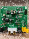
C4 (220pF 5% NP0) , R4 and R5 (10R) are the added components (ignore the double R2 designator, btw).
Congrats on figuring this out, you're a freakin' legend. :cool: This makes tons of sense.

C4 gets rid of the ultrasonic glitches but also acts like a massive amount of stray capacitance on the inverting input, hence the opamp response peaking at ~10 MHz you are seeing without the 100 ohms reduced.

In order to fix this properly, it may be helpful to introduce some series resistors after C4, say 100 ohms or so. (Not on the existing KTB obviously.) Also, this is not a new kind of problem, photodiode circuits and the like have had this for ages... let me consult my Art of Electronics for a sec. Yep, there it is. For those who have the 3rd edition of Horowitz/Hill, see sections 8.11.9/88.11.10, pp. 547-552. Hmm, not sure whether bootstrapping is going to help us though. It may help us out in getting 20 kHz distortion back down and keeping frequency response up, not so much at 10 MHz.

@KSTR, how do you think one should best model the ESS output, voltage source with resistors?
 
Last edited:
OP
KSTR

KSTR

Major Contributor
Joined
Sep 6, 2018
Messages
2,763
Likes
6,177
Location
Berlin, Germany
If you intend to "degrade" the D10B for comparison, how about add some impedance to the AVCC of the D10B ?
One of the differences may be that KTB uses the ADP150 for 3.3V and D10B uses the LM4562 as a 3.3V buffer for AVCC.

Edit: In D10B, It may be easy to connect the output of the 3.3V LDO (L33EK) around the ES9038Q2M IC directly to AVCC after removing the LM4562 for AVCC.
Yes, supply effects are unknown factors.
To check, I installed 10 ohms (!!) series resistance right after the caps (fed from the helper LM4563), the PCB invites this. Still with MC33078 installed.
The "normal" distortion rises a lot for a 240Hz -10dBFS signal but interestingly, the dirt tail doesn't change at all here:
1644058603806.png


From that I would conclude that resistive supply impedance to AVcc is not any critical for the 6-bit modulation pattern we see on the KTB.
But if we had a supply resonance at just the right frequency in the supply of the KTB things might be a bit different...
 
OP
KSTR

KSTR

Major Contributor
Joined
Sep 6, 2018
Messages
2,763
Likes
6,177
Location
Berlin, Germany
Congrats on figuring this out, you're a freakin' legend. :cool: This makes tons of sense.

C4 gets rid of the ultrasonic glitches but also acts like a massive amount of stray capacitance on the inverting input, hence the opamp response peaking at ~10 MHz you are seeing without the 100 ohms reduced.

In order to fix this properly, it may be helpful to introduce some series resistors after C4, say 100 ohms or so. (Not on the existing KTB obviously.) Also, this is not a new kind of problem, photodiode circuits and the like have had this for ages... let me consult my Art of Electronics for a sec. Yep, there it is. For those who have the 3rd edition of Horowitz/Hill, see sections 8.11.9/88.11.10, pp. 547-552. Hmm, not sure whether bootstrapping is going to help us though. It may help us out in getting 20 kHz distortion back down and keeping frequency response up, not so much at 10 MHz.

@KSTR, how do you think one should best model the ESS output, voltage source with resistors?
The moment you insert series resistance after the cross capacitor you are very close to a 2nd order filter so that's what I think is a good solution (mentioned above in a previous post).

Something like this, using a superbalanced filter setup (== fully differential):
1644059444441.png

Nice 2nd order Bessel LP for differential signal and enough of RF isolation resistance. OpAmp is happy but runs at somewhat higher noise gain at the top end. The self-biasing and zero AC CM voltage at the OpAmp pins are neat features.
DM input impedance is at flat 10R per leg, rising to 20R at 20kHz (with the 10R's removed it would be standard inductive slope). CM input impedance is high at 1660R per leg. Both might not actually degrade the performance, though (Okto, using a simple differential I/V with OPA1632, seems to have zero issues with the high CM impedance presented to the DAC chip).

As for modelling, you can use Thevenin as well as Norton equivalents, doesn't matter. Here I used the Norton equivalent but Thevenin is sometimes a bit more convenient (like for plotting input impedance).
 
Last edited:
OP
KSTR

KSTR

Major Contributor
Joined
Sep 6, 2018
Messages
2,763
Likes
6,177
Location
Berlin, Germany
I did some final experimenting on the "easy mod" for the KTB today and settled at slightly different compensation, still very similar to what I showed in post #99.

This time, additional 220pF caps go accross the original 806R feedback resistor whereas the 100R+470pF combo is left alone. And of course the cross-capacitor, also 220pF.
Mod.gif


Comparing to the stock behavior in the following plots.
Note that this is not the exact same physical channel modded vs. unmodded, rather it is from an untouched board and there will be some unit-to-unit variations but those are not large as I found (there is more left/right channel differences -- right is always a bit better, also seen on the D10B)

1kHz -20dBFS:
1kHz,-20dBFS.gif

A worthwile reduction even if the 2nd is a bit higher now, relatively speaking. The hash (>9th) is almost completely gone.

1kHz, 0dBFS:
1kHz,-00dBFS.gif

(ignore the 2.5kHz -100dBc marker, also in any following plots)
Generally 10dB than stock worse below 20kHz but still quite accecptable.

10kHz -20dBFS:
10kHz,-20dBFS.gif

2nd is a smidgen higher but all the rest is significantly reduced.

10kHz 0dBFS:
10kHz,-00dBFS.gif

Very similar to 1kHz, some 10dB worse in THD than stock.


====>
My summary would be that this mod (or the one in #99) is sufficiently effective in taming the obnoxious distortion pattern seen at ~-20dBFS levels, completely removing the THD+N "hump". Noise always dominates for lower generator levels than about -10dBFS.

If you tend to listen to loudness-war type of music at full bore then outcome is debatable (but won't matter anyway) but if it's more like well recorded acoustic Jazz or similar "soft and clean" music then I think it is not impossible that some really could hear an improvement, notably when there is also some input signal reduction in play (like from EQ or DRC or just as a simple volume control). Measured there is an improvement at any rate, even with the tradeoff at levels higher than -10dBFS.

And the mod is comparatively easy to install, no replacement of SMT components or OpAmps involved, only soldering on top of existing parts except for that cross capacitor. Nonetheless you will need some basic tools like magnifiers, fine solder tip, flux, good light and a calm hand and general experience with SMT parts... as well as some test capabilities to verify the improvment (loopback recording). Definitely not a first-time soldering/modding project.

It is true that opamp change to all OPA1612 plus fiddling around with more R/C values etc might improve things so much that we get close to KTB2 or even D10B performance levels. However, this kind of operation is less efficient in that even more skills and equipment is required to do it successfully. And it is not at all clear it really would improve things as dramatically as we would like to expect.
Hence I would be actually more inclined to redo the complete I/V on a piggy-back with all degrees of freedom and with benign (larger) SMT sizes.... way more fun... ;-)
 

Pdxwayne

Major Contributor
Joined
Sep 15, 2020
Messages
3,219
Likes
1,172
.....

If you tend to listen to loudness-war type of music at full bore then outcome is debatable (but won't matter anyway) but if it's more like well recorded acoustic Jazz or similar "soft and clean" music then I think it is not impossible that some really could hear an improvement, notably when there is also some input signal reduction in play (like from EQ or DRC or just as a simple volume control). Measured there is an improvement at any rate, even with the tradeoff at levels higher than -10dBFS.

.....
May I know when you do ABX with "well recorded acoustic Jazz or similar "soft and clean" music", to what would you specifically pay attention? Would you pay attention to echo trail? Would you listen for notes decays? Would you listen for harshness?

Also, have you tried doing loopback captures null comparisons using pkane‘s Deltawave app?

Thanks!
 

Grooved

Addicted to Fun and Learning
Joined
Feb 26, 2021
Messages
679
Likes
441
I did some final experimenting on the "easy mod" for the KTB today and settled at slightly different compensation, still very similar to what I showed in post #99.

This time, additional 220pF caps go accross the original 806R feedback resistor whereas the 100R+470pF combo is left alone. And of course the cross-capacitor, also 220pF.
View attachment 184422

Comparing to the stock behavior in the following plots.
Note that this is not the exact same physical channel modded vs. unmodded, rather it is from an untouched board and there will be some unit-to-unit variations but those are not large as I found (there is more left/right channel differences -- right is always a bit better, also seen on the D10B)

1kHz -20dBFS:
View attachment 184427
A worthwile reduction even if the 2nd is a bit higher now, relatively speaking. The hash (>9th) is almost completely gone.

1kHz, 0dBFS:
View attachment 184428
(ignore the 2.5kHz -100dBc marker, also in any following plots)
Generally 10dB than stock worse below 20kHz but still quite accecptable.

10kHz -20dBFS:
View attachment 184430
2nd is a smidgen higher but all the rest is significantly reduced.

10kHz 0dBFS:
View attachment 184431
Very similar to 1kHz, some 10dB worse in THD than stock.


====>
My summary would be that this mod (or the one in #99) is sufficiently effective in taming the obnoxious distortion pattern seen at ~-20dBFS levels, completely removing the THD+N "hump". Noise always dominates for lower generator levels than about -10dBFS.

If you tend to listen to loudness-war type of music at full bore then outcome is debatable (but won't matter anyway) but if it's more like well recorded acoustic Jazz or similar "soft and clean" music then I think it is not impossible that some really could hear an improvement, notably when there is also some input signal reduction in play (like from EQ or DRC or just as a simple volume control). Measured there is an improvement at any rate, even with the tradeoff at levels higher than -10dBFS.

And the mod is comparatively easy to install, no replacement of SMT components or OpAmps involved, only soldering on top of existing parts except for that cross capacitor. Nonetheless you will need some basic tools like magnifiers, fine solder tip, flux, good light and a calm hand and general experience with SMT parts... as well as some test capabilities to verify the improvment (loopback recording). Definitely not a first-time soldering/modding project.

It is true that opamp change to all OPA1612 plus fiddling around with more R/C values etc might improve things so much that we get close to KTB2 or even D10B performance levels. However, this kind of operation is less efficient in that even more skills and equipment is required to do it successfully. And it is not at all clear it really would improve things as dramatically as we would like to expect.
Hence I would be actually more inclined to redo the complete I/V on a piggy-back with all degrees of freedom and with benign (larger) SMT sizes.... way more fun... ;-)
Hi @KSTR , fantastic work!
Just curiosity but is it possible for you to do the same measurement at -1dBFS ? I noticed on the Tone2 Pro that there is a big difference between 0 and -1, then not so much between -1 and lower level

Would be curious to see results with Deltawave too ;-)
 
OP
KSTR

KSTR

Major Contributor
Joined
Sep 6, 2018
Messages
2,763
Likes
6,177
Location
Berlin, Germany
Addendum, Multitone in a restricted bandwidth at -10dBFS (for the peaks). Full bandwidth MT is not sensitive to the specific distortions we have, I've explained that in an earlier post.
MT30(20-600), -10dBFS.gif

20dB of wideband reduction of all the hash looks good to me ;-)
 
OP
KSTR

KSTR

Major Contributor
Joined
Sep 6, 2018
Messages
2,763
Likes
6,177
Location
Berlin, Germany
Hi @KSTR , fantastic work!
Just curiosity but is it possible for you to do the same measurement at -1dBFS ? I noticed on the Tone2 Pro that there is a big difference between 0 and -1, then not so much between -1 and lower level

Would be curious to see results with Deltawave too ;-)
10kHz @ -1dBFS:
1644084252978.png

No significant difference in harmonics to the 0dBFS plot.
 

Herbert

Addicted to Fun and Learning
Joined
Nov 26, 2018
Messages
529
Likes
435
Hervorragende Arbeit! So great!
Does it make sense playing around with the values of C4 / C3 and / or bridging / replacing
C2 / R1 with other values or is this "Ende der Fahnenstange"? (End of the Road)
 
OP
KSTR

KSTR

Major Contributor
Joined
Sep 6, 2018
Messages
2,763
Likes
6,177
Location
Berlin, Germany
Hervorragende Arbeit! So great!
Does it make sense playing around with the values of C4 / C3 and / or bridging / replacing
C2 / R1 with other values or is this "Ende der Fahnenstange"? (End of the Road)
Well, fine-tuning the values (and hookup) might give some improvement here and there, and some worsening at other operation points (frequency and level).

We are quickly entering the law of diminishing returns here and as you know too many tries resoldering on one and the same channel (to reduce unknowns) is prohibitive with this PCB, therefore I've not tested many combinations, like four or so. I found no easy way to reduce the distortion at lower levels (where it matters most) while not compromising some high level performance at the same time, that's the trade-off we have here.

For example, returning to #99 schematic, now with series R shorted and Cc = 470pF (twice the initial value) did almost change nothing and if anything then slightly to the worse. This also indicated by Spice analysis which also shows that the general range of usable values is restricted to avoid OpAmp stability and loading issues.
 

Herbert

Addicted to Fun and Learning
Joined
Nov 26, 2018
Messages
529
Likes
435
OK, thanks... Is there the possibility to repeat Amirs tests?
Just to see the difference at one glance and get an idea,
where it would land in the SINAD Score now...
 
OP
KSTR

KSTR

Major Contributor
Joined
Sep 6, 2018
Messages
2,763
Likes
6,177
Location
Berlin, Germany
My AP cannot do IMD test but the improvement is also seen in THD+N vs Level, depending on analyzer settings.

THD+N vs Level at 10kHz, 80kHz bandwidth:

1644156600099.png


THD+N degraded only by a dB or two at full scale output (as the noise contributes to the number as well even though harmonics are actually 10dB hotter with the mod).
Below -10dBFS there is constant improvement visible of up to some 5dB until -40dBFS where both are on par. Again, because of the baseline noise, the actual improvement of harmonics of up to 20dB is not visible, we only can see that the contribution must be lower than the noise floor but not by how much.
 

Herbert

Addicted to Fun and Learning
Joined
Nov 26, 2018
Messages
529
Likes
435
OK, so, bottom line:
Still an improvement possible, if somebody chimes in to replace the opamps, as their 8-pin
seems to work with the original 10 pin.
Hence I would be actually more inclined to redo the complete I/V on a piggy-back with all degrees of freedom and with benign (larger) SMT sizes.... way more fun... ;-)
First it did not seem to be a good idea but I would donate the parts for it - I assume the piggyback would as well help with awful boards like this,
cheapos from ebay:
 

Attachments

  • IMG_0618.jpg
    IMG_0618.jpg
    393.1 KB · Views: 156
OP
KSTR

KSTR

Major Contributor
Joined
Sep 6, 2018
Messages
2,763
Likes
6,177
Location
Berlin, Germany
OK, so, bottom line:
Still an improvement possible, if somebody chimes in to replace the opamps, as their 8-pin
seems to work with the original 10 pin.

First it did not seem to be a good idea but I would donate the parts for it - I assume the piggyback would as well help with awful boards like this,
cheapos from ebay:
That one could really be a nice donor platform. The circuit and layout for the digital sections look OK to me and are modding-friendly, as is the supply.
The analog section could be shut down completely and access to the chip's output pins is easy.
 

Pdxwayne

Major Contributor
Joined
Sep 15, 2020
Messages
3,219
Likes
1,172
I think I have found an electronic bass plus high hat test that can easily tell KTB apart from my X16.


From Windows 10 laptop via Firefox to Gustard x16 to Gustard H16 to Hifiman HE400se or AKG 371, the high hat sounded like high hat.

From Windows 10 laptop via Firefox to KTB to Gustard H16 to Hifiman HE400se or AKG 371, the high hat sounded like a clicking noise only and not like high hat.

Can someone please help check if you can reproduce what I found?

Thanks!

Update:
The clicking noise thing could be Firefox issue. Using chrome, no more just like a click. But, KTB now sounding much sharper in the hi-hat tone than x16 using either Firefox or Chrome.
 
Last edited:

gvl

Major Contributor
Joined
Mar 16, 2018
Messages
3,490
Likes
4,080
Location
SoCal
but if it's more like well recorded acoustic Jazz or similar "soft and clean" music then I think it is not impossible that some really could hear an improvement

How high is your confidence level these issues can in fact be audible considering that signs of the hump are not present with the multitone signal? Or did I misunderstand?
 
OP
KSTR

KSTR

Major Contributor
Joined
Sep 6, 2018
Messages
2,763
Likes
6,177
Location
Berlin, Germany
How high is your confidence level these issues can in fact be audible considering that signs of the hump are not present with the multitone signal? Or did I misunderstand?
Well, it depends on the specific mutitone's properties whether the error clearly sticks out from the noise floor or not. High level high frequency content sort of "dithers the effect away" in some cases. This is explainable mathematically, that is, we can model the unique distortion mechanism as a small but non-benign fast-wiggling static nonlinearity (oscillating 64 times around the linear slope) and show that this transfer curve with its "micro-roughness" has this interesting property -- and we could use this distortion modeller for simpler A/B-testing (future project).

The distortions manifest most easily with dominant lower level lower frequency content which is very typical range for real "normal" music, and the distortions are very unstable, shifting around their levels and structure like crazy with just a little change of the input signal. That creates a non-random noise floor, a noise-floor modulation with dirt signals that are somewhat chaotically dependent on and correlated to the signal. This does not mean higher frequency content isn't affected, indeed it is, simple single sine spectra already show it.

Sidenote: The exact effect on a typical music track, compared to a DAC that is benign and not showing any signs of the specific distortion, is still unclear... I'm working on that. The fact that the ESS resamples to its own private clock which is not steady as a rock doesn't make things easier.

I'm not claming this hump-creating specific distortion will be clearly audible immediately to most anybody, no way. This is not the case and it applies to 99% of error phenomena that are presented on this site, for DACs (and electronic gear in general).

Given that it is still a very unnatural form of distortion, though, I would be tempted to think our brains might have a harder timer to filter it away as easily as our benign "normal" distortion contributors which are more stable and much lower order distortion mechanisms. If there is any truth to "digital glare/harshness" etc effects that are claimed to be perceived by some, then this could be the thing we should look at, IMHO.
 
OP
KSTR

KSTR

Major Contributor
Joined
Sep 6, 2018
Messages
2,763
Likes
6,177
Location
Berlin, Germany
This is explainable mathematically, that is, we can model the unique distortion mechanism as a small but non-benign fast-wiggling static nonlinearity (oscillating 64 times around the linear slope) and show that this transfer curve with its "micro-roughness" has this interesting property -- and we could use this distortion modeller for simpler A/B-testing (future project).
I made good progress in writing such a simple distortion emulator and was able to very precisely imitate all of strange the distortion patterns, both the spectra and the distortion residuals (see post #1). The distortion is responsible for creating the "ESS hump" in THD+N/IMD+N plots as seen in some products like the Khadas Tone Board V1.3 and others.

Btw, "ESS hump" shall be considered a misnomer by now because we can be quite sure it's a problem in the analog output stage (the I/V-converter and subtractor circuit), not ahead of it. The chip itself is not to blame here.

I will open a new thread for this emulation approach and will present a small command-line program that adds the distortion to a .WAV file (which must be 24bit format), with a "zoom factor" option. By this we all can generate the authentic distortion on any of our music and can turn it up or down in level until we think it starts/stops being audible (assuming we use excellent DACs, AKM-based are preferred as those are completely free of that distortion). From this we may be able to infer if the hump's underlying mechanism has enough potential to be audible or not in practice.

When I now listen to the crazy distorted hashy dirt that will be added to softly recorded piano music like this ("Innocence") it is immediately clear that if this is really loud enough it will start to destroy the sound, make it fatigueing, less engaging and produce exactly that what I would personally associate to "digital glare".
 
Top Bottom