• WANTED: Happy members who like to discuss audio and other topics related to our interest. Desire to learn and share knowledge of science required. There are many reviews of audio hardware and expert members to help answer your questions. Click here to have your audio equipment measured for free!

Making my own RCA -> XLR cables

peng

Master Contributor
Forum Donor
Joined
May 12, 2019
Messages
5,723
Likes
5,297
My ground loop path was coming from the cable coax and being transferred via the hdmi cable. I could never find the cause of the cable coax other than disconnecting it all the way at where the cable was coming into the house.

Agree that grounding chassis isn’t always going to fix it, but definitely worth a shot. All you need is a good spot on each device and a piece of wire stripped to test it out.

But having a common ground for every device is always a good idea, so if your devices do not, doing that is always recommended.
Of course, I am not disagreeing with you in any sense. My point was simply that tying two chassis together won't always work for various reasons, for example, even if you tie them so well that there is only 1 micro volt difference in potential between the two, it does not mean that every point in the two devices that are connected to "ground" have the same potential as there are always resistance and/or impedance (tons of caps everywhere...) between two points. So, the better way is to try and determine where the loop is in the signal path itself and break the path(s).

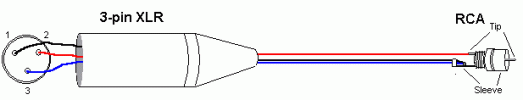
I got fixated on RCA to XLR because that's the title of your thread lol.., and I thought you focused on the right solution right from the beginning, that is again, break the ground loop currents in the signal path itself. It does not make doing it that way will eliminate ground loops, but it should eliminate, or more precisely, reduce the ground current flow in the signal path itself enough such that the hum will not be audible form your closest seats. Ground loop seems like a very fascinating topic as people typically have a lot to say about it when they see such posts.
 
Last edited:

L5730

Addicted to Fun and Learning
Joined
Oct 6, 2018
Messages
670
Likes
439
Location
East of England
Originally I was running RCA unbalanced cabled from an M-Audio PCI card on the old PC to Neutrik RCA-XLR adaptors which joined the ground to pin 3(?) +ve hot. Never heard a hum.

Exactly the same setup as far as the AC outlet for the new PC and the active monitors, but used Topping D10 USB DAC, same cables and got a low hum. I purchased Neutrik XLR connectors and just connected the signal to the XLR hot+, left everything else unconnected. No hum.
I also experimented with 'breaking the ground' on the USB, but found it was troublesome as it interfered with interface handshaking and could fry the USB chip in either the device or the PC. There should be safer ways to do this, I never tried the ifi Defender and didn't really want to provide external 5v power for a USB device.

I am now running balanced XLR cabled from RME Babyface Pro to active monitors, no modifications just a much much lower hum that I can't realistically hear unless the monitors are set flat out, and I am never gonna do that. My guess is that RME have implemented better isolation of internal grounds (analogue/digital) and thus caused some reduction in ground through.

I also had hum with a Raspberry Pi, but this was because it was connected to a TV via HDMI which was connected to main ground/earth. Run it headless and problem went away obviously.

A retired EE helped me diagnose ground loops with a multimeter.


I can't recall the XLR pinout but there are numerous documents, as well as it should be in the devices manual if not printed on the back of it, showing which is hot + , cold - and ground. Hook up RCA centre pin to +ve on xlr, and outside ring to ground by standard. Leave the - cold unconnected and properly shielded from either. If there is a ground loop hum, perhaps adding a resistor to the ground would help to reduce the current enough to make it inaudible. Else look to isolate the USB side with USB iso products, but watch out for that pesky USB packet noise ;)

As a side note, I have been hooking up another Topping D10 to the laptop (DC PSU, no mains ground) to the HiFi amp which has a plastic earth pin (3-pin UK plug). Occasionally I have gotten an immediate and obvious hum/buzz without much volume. Music played but it was clear there was a grounding problem. Turn amp down, unplug DAC USB cable, re-plug, all good.
 

rolltide

Member
Joined
Apr 5, 2024
Messages
8
Likes
1
Just to clarify, is this the correct wiring for an RCA output (i.e. Denon AVR-X3800H) to an XLR input (i.e. Buckeye Amps NC502MP) using a two conductor cable like the Mogami W2549?

xlr-rca.gif


XLR
  1. XLR Pin 1: Shield
  2. XLR Pin 2: Hot
  3. XLR Pin 3: Cold
RCA
  1. RCA Cup: Hot
  2. RCA Sleeve: Shield and Cold soldered together
 

Attachments

  • xlr-rca.gif
    xlr-rca.gif
    2.8 KB · Views: 5

rolltide

Member
Joined
Apr 5, 2024
Messages
8
Likes
1
XLR Pin 1 is the shield, you may not want to connect it to the RCA shell/sleeve.
Would it work better to jump Pin 1 and Pin 3 on the XLR connector?

xlr-rca2.gif


XLR
  1. XLR Pin 1: Shield (jumped to Pin 3)
  2. XLR Pin 2: Hot
  3. XLR Pin 3: Cold
RCA
  1. RCA Cup: Hot
  2. RCA Sleeve: Shield
 

Zek

Major Contributor
Joined
Feb 17, 2018
Messages
1,609
Likes
2,175
How does the signal flow, from XLR to RCA or from RCA to XLR?
If source is an XLR, then you should be careful if the source can be fried if it is connected to the RCA input in this way.
If RCA is the signal source, then this above remark is not important.
 

rolltide

Member
Joined
Apr 5, 2024
Messages
8
Likes
1
How does the signal flow, from XLR to RCA or from RCA to XLR?
If source is an XLR, then you should be careful if the source can be fried if it is connected to the RCA input in this way.
If RCA is the signal source, then this above remark is not important.
It will be for wiring an RCA output (Denon AVR-X3800H) to an XLR input (Buckeye Amps NC502MP).
 
  • Like
Reactions: Zek

Speedskater

Major Contributor
Joined
Mar 5, 2016
Messages
1,642
Likes
1,363
Location
Cleveland, Ohio USA
What would you recommend?

XLR

a. XLR Pin 1: Shield (Shield not Black)
b. XLR Pin 2: Hot (Red)
c. XLR Pin 3: Cold (Blue)

RCA

a. RCA Pin: Hot (Red)
b. RCA Sleeve: Cold (Blue)

Shield not connected to RCA

* * * * * * * * * * * * * *
Note ~as below.
It is best to use a Shielded Twisted Pair (STP) cable.
That way the only unbalanced part of the interconnect is the RCA plug.
 
Last edited:

Cbdb2

Major Contributor
Joined
Sep 8, 2019
Messages
1,554
Likes
1,534
Location
Vancouver
XLR

a. XLR Pin 1: Shield (Shield not Black)
b. XLR Pin 2: Hot (Red)
c. XLR Pin 3: Cold (Blue)

RCA

a. RCA Pin: Hot (Red)
b. RCA Sleeve: Cold (Blue)

Shield not connected to RCA
Yes. Which means using a shielded pair cable (shield plus 2 conductors), not coax.
 

Speedskater

Major Contributor
Joined
Mar 5, 2016
Messages
1,642
Likes
1,363
Location
Cleveland, Ohio USA
Note two:
The above is for a RCA output to an XLR input.
Because there are three & a half types of XLR output stages, no single arrangement will work for all three.
 

rolltide

Member
Joined
Apr 5, 2024
Messages
8
Likes
1
Note two:
The above is for a RCA output to an XLR input.
Because there are three & a half types of XLR output stages, no single arrangement will work for all three.

Yes, I'm trying to connect a Denon AVR-X3800H RCA pre-out to a Buckeye Amps NC502MP XLR input.

Hilariously not to scale, but does this illustration capture what you recommended above?

RCA output to an XLR input.png
 

sam_adams

Major Contributor
Joined
Dec 24, 2019
Messages
1,000
Likes
2,435
Follow Bill Whitlock's advice:

2conductorsor3.png


The capacitors in the diagram below represent the capacitance in the cable between the conductors and the conductors and the shield of the cable.

Balanced Lines – Ground at Driver or Receiver?.png


Use cable that has a twisted pair and a braided or served shield. Don't use a cable that has a twisted pair with a shield and a separate drain wire.

Everything you need to know—must know—about grounding and shielding is covered in Bill Whitlock's AES presentation below:

Bill Whitlock - An Overview of Audio System Grounding and Interfacing - Indy-AES-2012
 
Last edited:

rationaltime

Member
Joined
Jan 30, 2023
Messages
68
Likes
55
The single-ended signal conversion to balanced signal is done all the time
in the audio world. Typically this function is performed by a "direct box",
also called "DI". It is not done by any direct wiring of connectors.

Here is a schematic I copied from the Jensen Transformer web site.
Notice the single-ended input is on the right and the balanced output on the left.
DC connection from the input signal to the output is blocked.
Jensen_AS002.jpg


As you can see it is pretty simple. You could make your own, but you need the transformers.
Direct boxes of varying prices are available from a lot of manufacturers. The passive boxes
use this schematic or similar. You might even find something that fits your system from Jensen.
Browse the Jensen website for some inspiration.
 

Blumlein 88

Grand Contributor
Forum Donor
Joined
Feb 23, 2016
Messages
20,754
Likes
37,593
Follow Bill Whitlock's advice:

View attachment 364589

The capacitors in the diagram below represent the capacitance in the cable between the conductors and the conductors and the shield of the cable.

View attachment 364590

Use cable that has a twisted pair and a braided or served shield. Don't use a cable that has a twisted pair with a shield and a separate drain wire.

Everything you need to know—must know—about grounding and shielding is covered in Bill Whitlock's AES presentation below:

Bill Whitlock - An Overview of Audio System Grounding and Interfacing - Indy-AES-2012
So the equivalent to the GOOD version would be to use a shielded XLR cable for the whole run between power amp and preamp. Then on the RCA end use an RCA to male XLR adapter at the preamp output. Same basic result. Easy to do. Cheap shielded XLR cables from Monoprice would be fine for this. No need for you to custom connect or build your own adapter cables. The shield and pin 3 would only be connected just at the RCA plug by the adapter.
 
Last edited:
Top Bottom