• WANTED: Happy members who like to discuss audio and other topics related to our interest. Desire to learn and share knowledge of science required. There are many reviews of audio hardware and expert members to help answer your questions. Click here to have your audio equipment measured for free!

pma

Major Contributor
Joined
Feb 23, 2019
Messages
4,602
Likes
10,768
Location
Prague
They are FT 10MHz for the MJE and 60MHz for the BF-469/70 with 250V VCE. The BD-139/140 is 50Mhz.

I wouldn't use a Zetex transistor for anything- I just don't trust them. Back when Ferranti was Ferranti, but then they got sold out, restructured, sold again etc.

Anyway, just trying to help Pavel.

I appreciate it. However I have some experience as well, have been using simulations for 20 years and built amplifiers for 40years+, as you.

You are not right about BD139/140 fT. It is much, much higher in a real world parts and please see attached Philips datasheet. fT=160MHz. However the BD139/140 is not used here so why to bother.

Another point. It has to be stated that the circuit discussed here is not much of Luxman, but rather load-invariant Douglas Self topology just the CFP is not used. It will have far better parameters than the original Luxman. The amplifier world has not been frozen in 70's and 80's.

dself.png

Copyright @Douglas Self
 

Attachments

  • bd140.pdf
    48.8 KB · Views: 364

AnalogSteph

Major Contributor
Joined
Nov 6, 2018
Messages
3,373
Likes
3,318
Location
.de
You are not right about BD139/140 fT. It is much, much higher in a real world parts and please see attached Philips datasheet. fT=160MHz. However the BD139/140 is not used here so why to bother.
Ahem. Those Philips BD139/140s have not been made in donkey's years, since around the switchover to NXP branding in fact (early 2000s!). You can still get their surface mount versions in SOT-223 and SOT-89 though (something -53 and -56). The kind of BD139 you can still buy today will have Ic = 1.5 A and an fT of ~50 MHz or so. Just saying.
 

restorer-john

Grand Contributor
Joined
Mar 1, 2018
Messages
12,677
Likes
38,771
Location
Gold Coast, Queensland, Australia
My BD-139/BD-140s are Philips new old stock from the 1970s and 1980s. I have tons of original Philips semis and go by their rated specs from the time they were issued.

But I hardly use any Philips in anything much anymore. Most of my work is in Japanese silicon and I have some great sources for original components in Japan.
 

pma

Major Contributor
Joined
Feb 23, 2019
Messages
4,602
Likes
10,768
Location
Prague
Ahem. Those Philips BD139/140s have not been made in donkey's years, since around the switchover to NXP branding in fact (early 2000s!). You can still get their surface mount versions in SOT-223 and SOT-89 though (something -53 and -56). The kind of BD139 you can still buy today will have Ic = 1.5 A and an fT of ~50 MHz or so. Just saying.

Yeah, however the real world is such ..... :)

Scren111_d2.gif


Anyway, as I stated before, the debate on 139/140 is a bit pointless as I will not use them ;)

The more interesting point not mentioned enough is the role of the additional beta enhancing emitter follower in/before VAS - the key to considerable distortion reduction, higher LG and of course more issues with stability and the main reason why fast VAS transistors must be used to fix the stability. The result is worth doing that.

P.S.: I do not wish to spread more OT into this thread. I will open a dedicated thread after the amplifier functional sample is built.
 
Last edited:
OP
sabristol

sabristol

Member
Forum Donor
Joined
Feb 23, 2021
Messages
52
Likes
109
Hi @pma

Looking back at the thorough tests you've done on your amp, I selected these to do on my 'blameless' Luxman, excluding the preamp stage, so we can compare:
  • Slew rate 4R load @10kHz square wave ±12Vpk-pk
  • THD vs. Output
    • 4R load @1kHz, @200Hz, @5kHz
    • Capacitive load 4R//47nF @1kHz with and without 47nF
    • Torture load 4R//(0R47+3.3uF) @1kHz
  • CCIF IM @19kHz + @20kHz)
There's few chapters in CORDELL §25, §26 and §27 and SELF §15 that I should mug up on.

OK with you or is there a standard list you're aware of on this site that I should be using?

@restorer-john have you managed to find that magazine article with test results for the L-85V?

Regards,

S.
 

pma

Major Contributor
Joined
Feb 23, 2019
Messages
4,602
Likes
10,768
Location
Prague
Hi @sabristol ,

it is OK or we can agree on anything that might be suggested
Some thoughts:
  • Slew rate may be hidden because of the input RC lowpass action (slew rate and exponential rise time is not the same thing, slew rate means almost constant dv/dt as a result of charging usually Cdom capacitor by the current source) so it is uneasy to tell if it can be measured just at +/-12V. I would rather define rise time (10% - 90%) at the proposed +/-12V (24Vpp), as I am unwilling to de-solder parts from the finished amplifier
  • THD vs. output is OK
  • CCIF - let's define Vout [Vpp] swing, then it can be easily checked with a scope
  • I would add maximum power (continuous power defined as output Vrms*Vrms/Rload at THD<= 0.1%) that amp must be able to supply for at least 5 minutes continually - no "peak" power please
Note: I had some issues with the 1st sound card as it had similar H2 distortion as the amplifier under test and as a result the H2 was almost cancelled, which gave false optimistic THD results. This had been corrected by using another card, re-measured and re-posted.
 
Last edited:

restorer-john

Grand Contributor
Joined
Mar 1, 2018
Messages
12,677
Likes
38,771
Location
Gold Coast, Queensland, Australia

Attachments

  • L-85v review page 1 sml.pdf
    420.4 KB · Views: 360
  • L-85v review page 2 sml.pdf
    428.1 KB · Views: 335

pma

Major Contributor
Joined
Feb 23, 2019
Messages
4,602
Likes
10,768
Location
Prague
Yep, here it is. :)

Thank you, John. Am I right that they did not test with 4ohm load at all??? I would understand when I see only one output pair and high rails voltage, however I think that nowadays it is very rare to find a speaker with real 8 ohm impedance so the 8 ohm test is close to useless to me, these days.
 

restorer-john

Grand Contributor
Joined
Mar 1, 2018
Messages
12,677
Likes
38,771
Location
Gold Coast, Queensland, Australia
Am I right that they did not test with 4ohm load at all???

They did test with 4R, but not the full suite of tests. They only did all the tests if the manufacturer gave a 4R official rating.

1617603225612.png


They tested amplifiers according to the manufacturers rated minimum load and then did a half rated load individual L/R test. So we know it will put out 163W/ch single channel continuous.
 

Attachments

  • test conditions Po 2.pdf
    103.2 KB · Views: 216
  • test conditions Po 1.pdf
    503 KB · Views: 205

restorer-john

Grand Contributor
Joined
Mar 1, 2018
Messages
12,677
Likes
38,771
Location
Gold Coast, Queensland, Australia
@pma I like their overload recovery test. I have used it myself in the past with a toneburst gate I built (zero cross).
 

Attachments

  • overload recovery.pdf
    407.7 KB · Views: 218

pma

Major Contributor
Joined
Feb 23, 2019
Messages
4,602
Likes
10,768
Location
Prague
Hi @pma

Looking back at the thorough tests you've done on your amp, I selected these to do on my 'blameless' Luxman, excluding the preamp stage, so we can compare:
  • Slew rate 4R load @10kHz square wave ±12Vpk-pk
  • THD vs. Output
    • 4R load @1kHz, @200Hz, @5kHz
    • Capacitive load 4R//47nF @1kHz with and without 47nF
    • Torture load 4R//(0R47+3.3uF) @1kHz
  • CCIF IM @19kHz + @20kHz)
There's few chapters in CORDELL §25, §26 and §27 and SELF §15 that I should mug up on.

OK with you or is there a standard list you're aware of on this site that I should be using?

@restorer-john have you managed to find that magazine article with test results for the L-85V?

Regards,

S.

Hi @sabristol ,
here is the recent basic set as per your listing:

A250W_THD_4R_1k.png


A250W_THD_4R_200Hz.png


A250W_THD_4R_5kHz.png


A250W_CCIF2.png


A250W_CCIF_scope.png
 
OP
sabristol

sabristol

Member
Forum Donor
Joined
Feb 23, 2021
Messages
52
Likes
109
Yep, here it is. :)

Hello @restorer-john and @pma

Thanks for these - interesting. What magazine are they extracted from? The "recommended" looks like HiFi Choice used.

I'm just finishing a Luxman L-190 (pretty poor build quality) and then have a Trio receiver (a little bit better) to fix .... will test my L-85v soon after that :rolleyes:
 

restorer-john

Grand Contributor
Joined
Mar 1, 2018
Messages
12,677
Likes
38,771
Location
Gold Coast, Queensland, Australia
What magazine are they extracted from?

HiFi Choice's Amplifiers book. Over 50 amplifiers tested and reviewed. I also have the receivers one from the same period and it has 50 receivers too. Between my father and I we have a serious amount of magazines, reviews and in my case original brochures and documentation.

But this site has a phenomenal amount of audio and electronics magazines, carefully scanned and collated. And all free.

https://worldradiohistory.com/index.htm
 
OP
sabristol

sabristol

Member
Forum Donor
Joined
Feb 23, 2021
Messages
52
Likes
109
HiFi Choice's Amplifiers book. Over 50 amplifiers tested and reviewed. I also have the receivers one from the same period and it has 50 receivers too. Between my father and I we have a serious amount of magazines, reviews and in my case original brochures and documentation.

But this site has a phenomenal amount of audio and electronics magazines, carefully scanned and collated. And all free.

https://worldradiohistory.com/index.htm
Wow thanks for that John. I think it's about time I retired - I could get lost in there for hours.
 

pma

Major Contributor
Joined
Feb 23, 2019
Messages
4,602
Likes
10,768
Location
Prague
@pma I like their overload recovery test. I have used it myself in the past with a toneburst gate I built (zero cross).

I would add that seriously designed high power amplifiers MUST have DC output protection circuit that disconnects speaker under DC faulty conditions after precisely defined time. This was usually done with output relays, however the mechanical output relay is the most unreliable component of the well and safely designed amplifier. Mosfet SSR with high voltage/ current are the best solution. I think we have moved especially in power semiconductors since the seventies.
 

Jojo

Member
Joined
Jan 15, 2022
Messages
15
Likes
7
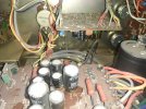
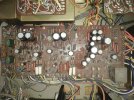
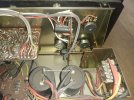
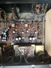
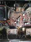
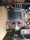
I had nice time reading you gentlemen. I have a luxman l-81 i cleaned up without touching anything electrically, that might had been touch by the ancient owner (i can see the power transistors were changed on one channel plus somes diodes that does not seems to be original. It works well on bookshelf speakers but there is a hum i can hear on the middle/tweeter (3 ways with supertweeter). I can't read a schematic like those you putted here, but i would like to know if you guys can confirm to me that someone did had work on my amp. I put some photos before cleaning ! Plus some documents i have for those luxman -- [ btw @restorer-john you Sir seems to know exactly how the l-81 works ! I saw in a thread (another one i think) you fixed one for your father ! :eek:]
There is the light bulb i've to change too, but i'm not sure about the voltage either (12v?).

For the story i was lucky to score it 30€ (in France) with b&w dm4 speakers at 50€. It was a happy day ! :D

I don't have the skills to read those schematic entirely and provide a good understanding if something happens, so here i am wanting to know if it is original by a better eye than mine. Anyway i find this amp to have a wonderfull sound compare to others vintage gear i heard, which makes me say to myself "don't let it die!"
 

Attachments

  • Luxman-L-80-V-Owners-Manual.pdf
    2.4 MB · Views: 152
  • IMG_20201116_121716.jpg
    IMG_20201116_121716.jpg
    259.7 KB · Views: 131
  • IMG_20201116_121659.jpg
    IMG_20201116_121659.jpg
    370.5 KB · Views: 114
  • IMG_20201116_121643.jpg
    IMG_20201116_121643.jpg
    299.9 KB · Views: 112
  • IMG_20201116_121601.jpg
    IMG_20201116_121601.jpg
    295.5 KB · Views: 111
  • IMG_20201116_121555.jpg
    IMG_20201116_121555.jpg
    288.5 KB · Views: 108
  • IMG_20201116_121550.jpg
    IMG_20201116_121550.jpg
    249.1 KB · Views: 120

restorer-john

Grand Contributor
Joined
Mar 1, 2018
Messages
12,677
Likes
38,771
Location
Gold Coast, Queensland, Australia
I had nice time reading you gentlemen. I have a luxman l-81 i cleaned up without touching anything electrically, that might had been touch by the ancient owner (i can see the power transistors were changed on one channel plus somes diodes that does not seems to be original. It works well on bookshelf speakers but there is a hum i can hear on the middle/tweeter (3 ways with supertweeter). I can't read a schematic like those you putted here, but i would like to know if you guys can confirm to me that someone did had work on my amp. I put some photos before cleaning ! Plus some documents i have for those luxman -- [ btw @restorer-john you Sir seems to know exactly how the l-81 works ! I saw in a thread (another one i think) you fixed one for your father ! :eek:]
There is the light bulb i've to change too, but i'm not sure about the voltage either (12v?).

For the story i was lucky to score it 30€ (in France) with b&w dm4 speakers at 50€. It was a happy day ! :D

I don't have the skills to read those schematic entirely and provide a good understanding if something happens, so here i am wanting to know if it is original by a better eye than mine. Anyway i find this amp to have a wonderfull sound compare to others vintage gear i heard, which makes me say to myself "don't let it die!"

It actually looks pretty much original, right down to the 45 year old dust, the odd spilled drink etc.

You mention hum. Is the hum common to both channels or just one? Is it dependant on volume setting or does it remain constant? Does the tone bypass/defeat function change the hum level?

The original Nippon Chemicon black electrolytics are usually pretty reliable, however Lux has glued several of the large ones down and corrosion of the leads under the capacitors is a very common issue. There is one that has a significant lean on it- it could be OK, but it could also be the rubber seal swelling and lifting the cap. Those old caps have their vents on the base, not the top like modern caps. I have arrowed the one I don't like the look of.
1642890267704.png

Down the track, you need to have the four red arrowed components replaced with twin diode strings (2x1N4148). They are an epoxy 'blob' varistor diode and they are failure prone. When they become intermittent, the amp will go in and out of protection and then possibly fail altogether.

The Lux L-81 is a great vintage integrated amplifier- very beautiful to look at, nicely made and very reliable. They are also worth a lot on the 2nd hand market. Enjoy!
 

DSJR

Major Contributor
Joined
Jan 27, 2020
Messages
3,386
Likes
4,521
Location
Suffolk Coastal, UK
Very late reply regarding the T88-V tuner - would be interesting to discover what yiou/the OP thinks of it. I bought a mint one to 'replace' a Revox A76 which looked ugly but which 'sounded' superb and in comparison, the Luxman tuner sounded very muffled. No expertise or facilities to check anything, but it was so bad I wondered if the FM de-emphasis was set incorrectly...

Loved the L-85V when it was new. Powerful for the times but with a subjective velvet glove that enchanted most who heard and used them.
 

NiagaraPete

Major Contributor
Forum Donor
Joined
Jun 23, 2021
Messages
2,190
Likes
1,960
Location
Canada
You are my new hero. I love old Lux and bringing one back from the dead gives you god status in my books.
 

Doodski

Grand Contributor
Forum Donor
Joined
Dec 9, 2019
Messages
21,543
Likes
21,828
Location
Canada
You are my new hero. I love old Lux and bringing one back from the dead gives you god status in my books.
The old Luxman Champagne Series with large square buttons does it for me. I've seen thousands of stereo packages and always looked twice at that stuff when walking by and hanging out. With those big meters and stuff. Oh YeaH! :D
 
Top Bottom