• WANTED: Happy members who like to discuss audio and other topics related to our interest. Desire to learn and share knowledge of science required. There are many reviews of audio hardware and expert members to help answer your questions. Click here to have your audio equipment measured for free!

KEF R3 meta Measurements

thewas

Master Contributor
Forum Donor
Joined
Jan 15, 2020
Messages
6,895
Likes
16,896
It's a while ago so I can't remember exactly which components are in the graphs. But yes, electrolytic capacitors have easily measurable distortion and the distortion level varies from manufacturer to manufacturer for components with exactly the same spec. in Fig 54 the red and greed are most certainly two different types of electrolytic cap. I suspect the blue is a PP cap (PP caps all have very low distortion indeed). Cored inductors also have easily measurable distortion but there's big variation for components with the same specification depending on the core type, geometry and material.
But for foil capacitors and coreless inductors which are long and commonly used for mid or high frequency range the distortion magnitudes and differences are so low that they are inaudible, right?
 

Koeitje

Major Contributor
Joined
Oct 10, 2019
Messages
2,306
Likes
3,965
Did you mean there are audible differences outside the measured parameters mostly discussed here ?
The distortion levels you see are within hearing range for the bad components.
 

jackocleebrown

Member
Technical Expert
Audio Company
Joined
Jan 30, 2020
Messages
74
Likes
1,017
Location
UK
What were the filter frequencies for these tests? I'm guessing the distortion is highest at what would be the crossover frequency, and not at a frequency that is rolled off.
Sorry, it was a long time ago so I can't remember the set up for these specific tests. However, in general output distortion is seen at frequencies where there is significant current carried by the "poor" component. For example, if you have a 2nd order high pass then the capacitor is in series with the load and distortion generated by the capacitor will be seen in the passband. The inductor is in parallel with the load and only carries significant current around the roll-off frequency so you see a peak in the distortion. My guess is that Fig 55 shows distortion due to a cored inductor used on a 2nd order high-pass xover.
 

jackocleebrown

Member
Technical Expert
Audio Company
Joined
Jan 30, 2020
Messages
74
Likes
1,017
Location
UK
But for foil capacitors and coreless inductors which are long and commonly used for mid or high frequency range the distortion magnitudes and differences are so low that they are inaudible, right?
Air core inductors and foil capacitors are extremely linear. It's extremely difficult to measure any distortion from them. I'd be interested to try again now with some better test equipment... I expect there is some distortion there and my guess is that they're not as linear as a modern DAC. If I have some time I will try and do this. However, the majority of loudspeakers use at least some electrolytic and some cored inductors. Especially if they are 3-way designs. Large value air core inductors and film capacitors are extremely large and expensive.
 

thewas

Master Contributor
Forum Donor
Joined
Jan 15, 2020
Messages
6,895
Likes
16,896
However, the majority of loudspeakers use at least some electrolytic and some cored inductors. Especially if they are 3-way designs. Large value air core inductors and film capacitors are extremely large and expensive.
Yes, but they use them typically on the woofer or parallel branches where audibility thresholds are quite higher.

Air core inductors and foil capacitors are extremely linear. It's extremely difficult to measure any distortion from them. I'd be interested to try again now with some better test equipment... I expect there is some distortion there and my guess is that they're not as linear as a modern DAC.
I think it would be also interesting to not only measure but also record the outputs with different components and test their audibility in an AB test.
 

jackocleebrown

Member
Technical Expert
Audio Company
Joined
Jan 30, 2020
Messages
74
Likes
1,017
Location
UK
Yes, but they use them typically on the woofer or parallel branches where audibility thresholds are quite higher.
Anything over 10uF or 0.5mH is most likely going to be an electrolytic or cored inductor except in very expensive loudspeakers. 3-way speakers almost always need a big series cap on the MF. With higher order crossovers you get bigger series values too. Playing around with a "text book" crossover calculator gives a reasonable idea:

1680107994344.png

1680108083883.png
 

thewas

Master Contributor
Forum Donor
Joined
Jan 15, 2020
Messages
6,895
Likes
16,896
Anything over 10uF or 0.5mH is most likely going to be an electrolytic or cored inductor except in very expensive loudspeakers. 3-way speakers almost always need a big series cap on the MF. With higher order crossovers you get bigger series values too. Playing around with a "text book" crossover calculator gives a reasonable idea:

View attachment 275715
View attachment 275716
Yes, it is true that for such a low cross frequency the capacitance value can be quite high and for example an 82 uF MKT can cost around 30€ which is too high for a not too highly priced loudspeaker, in DIY we unfortunately tend to ignore such issues.

On the other hand some here performed multitone distortion measurements with a driver below show no significant differences between foils and electrolytics, would like to hear your comments on it:


Also what do you think about the choice some do adding a small parallel foil cap to an electrolytic to reduce the ESR, does it also reduce the distortion?

Thank you for your highly valued contributions here. :)
 

Alexx

Active Member
Joined
Jan 26, 2022
Messages
182
Likes
68
I'm not a great expert on the subject.

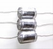
But there is a small difference between a 30 cent condenser and a 10 euro one (insulation quality, tolerance, etc. ) perhaps this also affects the sound......?

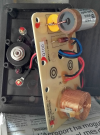
Many times we stick to the power/signal cable (this is more debatable) but the crossover being the main sound processing center of the speaker itself, if made with poor or first-order material, a difference in performance is more than plausible.

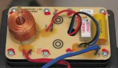
Then everyone can think as he wants, I won't discuss this, but in electronics capacitors, resistors, coils and anything else, if made and built with a poor or excellent level, can make a difference.
See you soon.
 

Mnyb

Major Contributor
Forum Donor
Joined
Aug 14, 2019
Messages
2,765
Likes
3,839
Location
Sweden, Västerås
What about tolerances especially caps who can be all over the place ? getting higher quality can possibly assure better production tolerances for the whole product .

Or can one be forced to chose a crossover design who is less sensitive for tolerance mismatches ? I can imagine trying some deep high Q notch filters and miss the target frequency :)
 

Beave

Major Contributor
Joined
May 10, 2020
Messages
1,390
Likes
3,014
Just going to leave this here:
View attachment 275672

As others have asked, are we supposed to believe an additional 0.25% THD at 30-40Hz is audible (first graph)?

And the second graph showing a 0.3% increase in midrange THD (maybe barely audible?) using what *might* be cored inductors and electrolytic caps on the highpass filter when, I dare say, most speakers don't use cored inductors or electrolytics on the tweeter highpass?

I'm no crossover designer, but this looks like marketing sleight-of-hand more than engineering.
 

maty

Major Contributor
Joined
Dec 12, 2017
Messages
4,600
Likes
3,170
Location
Tarragona (Spain)
Years ago I was also very skeptical but one day I decided that I would check it for myself, with my KEF Q100 (excellent driver, cheap implementation and with poorly designed front bass-reflex).

First I tried some cheap styroflex capacitors to make the bypass. It improved the sound but not dramatically.

Months later I decided to change them for a Miflex and the difference was SPECTACULAR, as I mentioned at the time in the forums of diyaudio.com (the first test was with Hotel California, Eagles). Then I changed the resistor for a Mills, and it was noticeable but not so much. Old picture below.

Later I made other improvements, such as two layers of viscoelastic material (Tecsound SY70) to minimize vibrations from the cabinet. I was doing the best step by step to verify if they were effective. And...

In short, my modified KEF Q100 sound much better than the originals, much better without any doubt.
 

Attachments

  • LOT 3 Condensateurs Styroflex - NEUFS 10nF - 600V - 0.010uF - 10000pF - 10%.jpg
    LOT 3 Condensateurs Styroflex - NEUFS 10nF - 600V - 0.010uF - 10000pF - 10%.jpg
    88.3 KB · Views: 58
  • KEF-Q100-crossover-with-Mills-06R8-5-watts-resistor.png
    KEF-Q100-crossover-with-Mills-06R8-5-watts-resistor.png
    1.1 MB · Views: 72
  • KEF-Q100-crossover.jpg
    KEF-Q100-crossover.jpg
    113.5 KB · Views: 61

Mnyb

Major Contributor
Forum Donor
Joined
Aug 14, 2019
Messages
2,765
Likes
3,839
Location
Sweden, Västerås
As others have asked, are we supposed to believe an additional 0.25% THD at 30-40Hz is audible (first graph)?

And the second graph showing a 0.3% increase in midrange THD (maybe barely audible?) using what *might* be cored inductors and electrolytic caps on the highpass filter when, I dare say, most speakers don't use cored inductors or electrolytics on the tweeter highpass?

I'm no crossover designer, but this looks like marketing sleight-of-hand more than engineering.
I think it's good design hygiene to avoid obvious problems if it's "just" about picking similarly priced components with better performance :) and the cr*p will add up somewhere if every component in your chain is on the edge of having audible problems the end result may suffer ?
 

dogmamann

Addicted to Fun and Learning
Joined
Dec 16, 2022
Messages
817
Likes
513
Years ago I was also very skeptical but one day I decided that I would check it for myself, with my KEF Q100 (excellent driver, cheap implementation and with poorly designed front bass-reflex).

First I tried some cheap styroflex capacitors to make the bypass. It improved the sound but not dramatically.

Months later I decided to change them for a Miflex and the difference was SPECTACULAR, as I mentioned at the time in the forums of diyaudio.com (the first test was with Hotel California, Eagles). Then I changed the resistor for a Mills, and it was noticeable but not so much. Old picture below.

Later I made other improvements, such as two layers of viscoelastic material (Tecsound SY70) to minimize vibrations from the cabinet. I was doing the best step by step to verify if they were effective. And...

In short, my modified KEF Q100 sound much better than the originals, much better without any doubt.
Without THD measurements, it can be just placebo. I had “heard” differences between soldering wire brands when I did DIY. Now when I look back, I realize it was all in my head. Suddenly one day if I blindly listen them, I cannot tell them apart
 

Mnyb

Major Contributor
Forum Donor
Joined
Aug 14, 2019
Messages
2,765
Likes
3,839
Location
Sweden, Västerås
I do appreciate Kef's musings about xover components . They actually show real performance with measurement and its' not about super expensive voodoo stuff like paper in oil caps with silver foil and such stuff . It may not be audible but it's good engineering practice.
 

maty

Major Contributor
Joined
Dec 12, 2017
Messages
4,600
Likes
3,170
Location
Tarragona (Spain)
Without THD measurements, it can be just placebo. I had “heard” differences between soldering wire brands when I did DIY. Now when I look back, I realize it was all in my head. Suddenly one day if I blindly listen them, I cannot tell them apart
What do you understand by SPECTACULAR? Undeniable for anyone. We were two people and we hallucinated. Logically, one box was first modified and compared with the other.

Step by step
, to verify the possible differences.
 

BrokenEnglishGuy

Major Contributor
Joined
Jul 19, 2020
Messages
1,936
Likes
1,158
What do you understand by SPECTACULAR? Undeniable for anyone. We were two people and we hallucinated. Logically, one box was first modified and compared with the other.

Step by step, to verify the possible differences.
What do you understand by just placebo?
 

dogmamann

Addicted to Fun and Learning
Joined
Dec 16, 2022
Messages
817
Likes
513
What do you understand by SPECTACULAR? Undeniable for anyone. We were two people and we hallucinated. Logically, one box was first modified and compared with the other.

Step by step, to verify the possible differences.
measure modeified box vs non modified and show the difference. Simple
 

dogmamann

Addicted to Fun and Learning
Joined
Dec 16, 2022
Messages
817
Likes
513
What do you understand by SPECTACULAR? Undeniable for anyone. We were two people and we hallucinated. Logically, one box was first modified and compared with the other.

Step by step, to verify the possible differences.
Could be spectacular for your ears, (can be just placebo)but since it’s not evidence backed, no reason to believe it.
 

dogmamann

Addicted to Fun and Learning
Joined
Dec 16, 2022
Messages
817
Likes
513
What do you understand by SPECTACULAR? Undeniable for anyone. We were two people and we hallucinated. Logically, one box was first modified and compared with the other.

Step by step, to verify the possible differences.
If you modify components, it a possible that the newly bought components may have a bette for worse tolerance than the Orginal parts meaning one of them(Orginal or the ones you modified), may be working not exactly at the value printed on them. Hence they can sound different. Difference can be spectacular or meh depending on what your preferences are.
 

Kachda

Addicted to Fun and Learning
Forum Donor
Joined
May 31, 2020
Messages
909
Likes
1,615
Location
NY
Years ago I was also very skeptical but one day I decided that I would check it for myself, with my KEF Q100 (excellent driver, cheap implementation and with poorly designed front bass-reflex).

First I tried some cheap styroflex capacitors to make the bypass. It improved the sound but not dramatically.

Months later I decided to change them for a Miflex and the difference was SPECTACULAR, as I mentioned at the time in the forums of diyaudio.com (the first test was with Hotel California, Eagles). Then I changed the resistor for a Mills, and it was noticeable but not so much. Old picture below.

Later I made other improvements, such as two layers of viscoelastic material (Tecsound SY70) to minimize vibrations from the cabinet. I was doing the best step by step to verify if they were effective. And...

In short, my modified KEF Q100 sound much better than the originals, much better without any doubt.
Do you have any measurements that prove these claims?
 
Top Bottom