Thanks. Now I see, sound is going both ways. Some stout construction is needed otherwise.That is sometimes done, but you need a convenient room behind them.

-
WANTED: Happy members who like to discuss audio and other topics related to our interest. Desire to learn and share knowledge of science required. There are many reviews of audio hardware and expert members to help answer your questions. Click here to have your audio equipment measured for free!
You are using an out of date browser. It may not display this or other websites correctly.
You should upgrade or use an alternative browser.
You should upgrade or use an alternative browser.
Is baffle shape really important? What about these ideas?
- Thread starter GM3
- Start date
Well, or a common old cabinet. My 15" woofers take 3 cubic feet, for example.Thanks. Now I see, sound is going both ways. Some stout construction is needed otherwise.
It can be done as the wall height can be utilised to increase the enclosure volume. I use two of these in-wall subs and they can compete with many freestanding subs.How do you get the requisite box volume? Unless you mean the infinite baffle drivers with 0.707 Qts. That is sometimes done, but you need a convenient room behind them.
SSW-3 | Dual 10" (250mm) Passive In-Wall Subwoofer
The SSW-3 is an in-wall subwoofer system designed to deliver powerful and accurate low frequency response while remaining hidden from view. It features dual 10-inch (250mm) cast-frame woofers mounted in a heavily-braced Sonoglass molded baffle and an MDF Enclosure that installs into standard 2x6...
 www.jblsynthesis.com
The biggest problem with in wall speakers is simply that not a lot of people buy them, so there's a limited selection and not a lot of top-quality stuff. I assume the JBL, Genelec, KEF and Revel stuff is okay but not as good as their floor speakers.
If you're trying to fit a speaker into a stud cavity you're bound to run into problems. Many of them don't have an enclosure at all.
In North America, a stud wall is basically 4" deep if you measure from the front surface, which is barely enough room for a good midwoofer, to say nothing for a decent 8" woofer or bigger.
So, in theory, quite easily achievable. Easy to do if you are building your own wall (great soffit mounted main monitor options from ADAM, Genelec, Dynaudio, Augsperger, Meyer, whatever you like). In practice, there are some challenges, especially if you're on a normal budget.
My dream listening room would be have big corner chamfers smoothly bridging the side and back wall. I would build it out of 2x6 all sistered up against each other, and I'd overbuild the hell out of it with plywood, bituminous damping, green glue, whatever else. Then I would machine a big flush mount baffle out of aluminum plate laminated between baltic birch. I would design a frame for invisible grilles. Run the amps in another room. Or, alternately, just get some of the bigger genelecs.
OK, now we just need in-wall speakers from about 100Hz up.It can be done as the wall height can be utilised to increase the enclosure volume. I use two of these in-wall subs and they can compete with many freestanding subs.
SSW-3 | Dual 10" (250mm) Passive In-Wall Subwoofer
The SSW-3 is an in-wall subwoofer system designed to deliver powerful and accurate low frequency response while remaining hidden from view. It features dual 10-inch (250mm) cast-frame woofers mounted in a heavily-braced Sonoglass molded baffle and an MDF Enclosure that installs into standard 2x6...
OK, now we just need in-wall speakers from about 100Hz up.

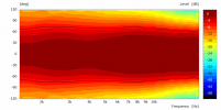
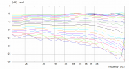
Official KEF Ci5160REF -THX spinorama
I am in the process of replacing my JBL C222HP LCR speakers with KEF Ci5160REF -THX. I asked KEF to send me the spinorama chart. It took them a while but the delay turned out to due to their updating the model to THX spec. I thought the chart will be valuable information for the forum. I have...
www.audiosciencereview.com
Not bad at all.Official KEF Ci5160REF -THX spinorama
I am in the process of replacing my JBL C222HP LCR speakers with KEF Ci5160REF -THX. I asked KEF to send me the spinorama chart. It took them a while but the delay turned out to due to their updating the model to THX spec. I thought the chart will be valuable information for the forum. I have...
So now we're down to WAF.
It's better, but obviously baffle step correction is not that evil.So we come back to where I was trying to go. Is the infinite baffle FAR superior to the diffraction baffle affects found in most speaker or just aesthetics.
@fpitas Beat me to it
What are the common flaws [of in-wall speakers]? I would guess that the room size and geometry would be the biggest impediment, no?
With flush-mounted speakers there is no reflection coming from a wall behind the speakers which imo is a significant advantage from a boundary interference standpoint, and the absence of that delayed front-wall reflection improves the perception of soundstage depth.
The correct toe-in angle would need to be built into the wall, which is what studios do.
I'm currently working on some large custom flush-mounted speakers for a recording studio, and the toe-in angle is built into the walls. Needless to say, these are not the 4" deep walls you find in typical home construction.
I just wanted to chime in that I may have understated the effectiveness of sims for horns / waveguides. Of course the modeling tools available (irrespective of price) are capable of modeling the behavior of tweeters and then some.if one can model a hypersonic aircraft wing, one should be able to pin down an acoustic lens. The assessment provided suggested it just isn't so,
However, I think for the DIYer, the free tools out there (ATH) are 1) not necessarily useful for completely arbitrary sims and 2) getting the exact measurements of every bit of th driver into the sim such that the output is also exactly correct is somewhat difficult.
So, basically, completely possible in theory, but tricky in practice.
JRS
Major Contributor
It was an interesting exchange. We all know the tech has enormous potential. But likely also requires a huge amount of work to get things sorted and productive. Be a great project for a club where one might have access to different sorts of expertise and the time burden shared. In the meantime, maybe companies will follow the led of SB Acoustics who offer their top of the line Be tweeter in 2 flavors--naked and lensed. Only 300 w/o the WG, 500 with. tho I'd like to see that difference shaved.I just wanted to chime in that I may have understated the effectiveness of sims for horns / waveguides. Of course the modeling tools available (irrespective of price) are capable of modeling the behavior of tweeters and then some.
However, I think for the DIYer, the free tools out there (ATH) are 1) not necessarily useful for completely arbitrary sims and 2) getting the exact measurements of every bit of th driver into the sim such that the output is also exactly correct is somewhat difficult.
So, basically, completely possible in theory, but tricky in practice.
It's actually remarkably simple when you understand it, but it does take time and effort to get there. For many people that does make it only possible in theorySo, basically, completely possible in theory, but tricky in practice.
")
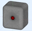
To get the best result the system needs to be designed to function together. Here is an example of a waveguide for the T34A that works really well in a freestanding cabinet. The same waveguide is pretty horrible in an infinite baffle. Horses for courses.
Attachments
I'll back up fluid here. If you can make a certain set of assumptions it is fully possible for the dedicated hobbyist to quite accurately simulate these things. The fewer assumptions you want to (or can) make, the more complex it gets. Assuming pistonic motion and rigid boundaries gets you really far, and for the right kind of tweeter that is pretty much accurate up until the last octave at least. Simulating accurately at very high frequencies or with non-pistonic sources is where the need for multiphysics-capable software arises, and with that comes increased complexity for the operator.
A big thanks also has to be given to Jörg Panzer, who is kind enough to make incredibly powerful software like AKABAK/ABEC free for hobbyists like ourselves. You'd see way less of these things if people had to pay thousands for a license.
A big thanks also has to be given to Jörg Panzer, who is kind enough to make incredibly powerful software like AKABAK/ABEC free for hobbyists like ourselves. You'd see way less of these things if people had to pay thousands for a license.
Right, my comments are mainly about the fact that the response tends to fall apart above 10khz, especially when certain details of the geometry of the tweeter are only approximated, not exact.or the right kind of tweeter that is pretty much accurate up until the last octave at least.
Again, my comments are mainly based on what I've observed on DIYAudio and not from experience! I'm hoping to dive into some sims of my own in the near future, on the other hand that T34A WG might be the ticket already
There is some truth to this. To model a dome tweeter the dimensions of the dome and surround, the dimensions used need to be quite accurate and small changes can have quite an effect. So you cannot reliably make a generic waveguide if high performance is a goal. Hard domes are much easier to simulate accurately as they more closely resemble the assumption of a pistonic membrane. A soft dome tweeter will not behave in this way and at different frequencies the membrane will radiate differently from different parts and to simulate this, FEM and the multiphysics type approach is necessary to get an accurate answer. For compression drivers it depends on the design of the phase plug as to whether the phase plug is working to produce a flat wavefront or not and up to what frequency. Many compression drivers produce a flat wavefront up to 10K or so, this will change with the size of the driver too, beyond that the assumption of a flat wavefront from a flat driving surface may not hold true and become inaccurate. Then a more complete model of the phase plug and material properties will be needed to have a more accurate simulation. Some drivers don't produce a flat wavefront even at much lower frequencies and so any simulation assuming a flat wavefront will have some error.Right, my comments are mainly about the fact that the response tends to fall apart above 10khz, especially when certain details of the geometry of the tweeter are only approximated, not exact.
Having said all of the above, being able to simulate fairly accurately up to 10K is plenty enough in practice. What happens beyond there is not so wildly different and unpredictable as to cause any device to behave poorly in practice due to simulation inaccuracy.
I don't know how you came up with these graphic, but but if validated, it is a very convincing argument for spherical loading of drivers. Elipson in the early 50's were the main proponents. Spherical loading will also result in a more even piston back pressure on the driver's. excursion.
I don't know how you came up with these graphic, but but if validated, it is a very convincing argument for spherical loading of drivers. Elipson in the early 50's were the main proponents. Spherical loading will also result in a more even piston back pressure on the driver's. excursion.
See page 2 and 3. These are theoretical and greatly exaggerated compared to a real life situation. A properly designed rectangular box works perfectly fine without the severe problems these graphics imply.
My understanding is that Harry Olsen's diffraction behavior graphs were based on assumptions, not actual measurements, and that one of the assumptions was the radiation pattern behavior of a hypothetical 1" fullrange driver.See page 2 and 3. These are theoretical and greatly exaggerated compared to a real life situation. A properly designed rectangular box works perfectly fine without the severe problems these graphics imply.
Similar threads
- Replies
- 24
- Views
- 2K
- Replies
- 19
- Views
- 2K
- Replies
- 77
- Views
- 7K