• Welcome to ASR. There are many reviews of audio hardware and expert members to help answer your questions. Click here to have your audio equipment measured for free!

Introducing DSPi | A powerful, user friendly and open source DSP for less than a cup of coffee

I was setting up my system and had a rather indiscreet question. Is there no 88.2 kHz support because no one needs it? Or is there some problem with it? It would be very convenient to not change all frequencies <=96 kHz and downsample all frequencies >=96 kHz.

I hope to make Linux and RPi users very happy soon. Hint hint!
Wow. Super :) .
 
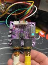
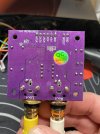
I'm having trouble getting audio out of this DAC board.

Data = GPIO 6
BCK = GPIO 14
LRCK = GPIO 15
5v and GND to PSU
MCLK = floating because this board has it's own TeraDak oscillator.

Output is configured to i2s on the correct pins, matrix is setup correctly. I see signal coming in and out of the console, but no audio output.

1788110558981.png

1788110580528.png

1788110599490.png


What am I missing?
 

Attachments

  • IMG_0790.jpg
    IMG_0790.jpg
    281.4 KB · Views: 146
  • IMG_0788.jpg
    IMG_0788.jpg
    243.4 KB · Views: 140
I'm having trouble getting audio out of this DAC board.

Data = GPIO 6
BCK = GPIO 14
LRCK = GPIO 15
5v and GND to PSU
MCLK = floating because this board has it's own TeraDak oscillator.

Output is configured to i2s on the correct pins, matrix is setup correctly. I see signal coming in and out of the console, but no audio output.

View attachment 555379
View attachment 555380
View attachment 555381

What am I missing?
I think I had a bad board. The second DAC is working. All good so far!
 
DSPi doesn’t pass SPIDIF input through ASRC. Instead it recovers the clocks and then uses them to servo the PIO output dividers; both for SPDIF, I2S and ADAT outputs. All output slots are sample aligned for SPDIF and ADAT (DSPi slave mode) inputs.
So the sample rate and subsequent I2S clocks are synced to SPDIF?
 
DSPi doesn’t pass SPIDIF input through ASRC. Instead it recovers the clocks and then uses them to servo the PIO output dividers; both for SPDIF, I2S and ADAT outputs. All output slots are sample aligned for SPDIF and ADAT (DSPi slave mode) inputs.
So just to clarify my limited understanding

I've been trying to research HowTo get BNC Word Clocking integrated with I2S clocking without spending $100's on specialised devices

not just for DSPi use but in general.

However, with multiple DSPi specifically, please confirm

if feeding them ADAT or S/PDIF (TOSlink or Coax)

so long as the source devices are all kept in sync via BNC Word Clock

no need to further worry about clock sync between DSPi units?

Time taken by processing, time of flight delays etc can be handled separately, here I'm just asking about preventing clock drift.

Also, is the answer the same for AES3 input?

If anyone can help at at all with the "big picture" top research project, if it's OT to DSPi specifically, please start a new thread, or post here

 
DSPi Console does not run on a Windows 10 Virtualbox VM. It doesn't throw any error, it just doesn't run. I've install dotnet framework.
 
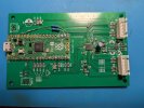
I successfully configured and ran DSPi with an ES9081 DAC. I'm feeding MCLK from a separate crystal. All 8 channels work perfectly.
Ignore the messy soldering and resistors, it's a test board.
 

Attachments

  • PXL_20260901_102938542.jpg
    PXL_20260901_102938542.jpg
    458.1 KB · Views: 209
Very nice. Did you managed to get it done on only two layers?
What LDO are you using?
 
I successfully configured and ran DSPi with an ES9081 DAC. I'm feeding MCLK from a separate crystal. All 8 channels work perfectly.
Ignore the messy soldering and resistors, it's a test board.
Great choice for a budget multichannel DAC!
 
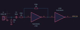
I added a rotary encoder for volume and mute and it works perfectly. However SPDIF doesn't, DSPi doesn't even register any incoming signal. I probed the signal and it's 1VRms, might that be too low?
 
I added a rotary encoder for volume and mute and it works perfectly. However SPDIF doesn't, DSPi doesn't even register any incoming signal. I probed the signal and it's 1VRms, might that be too low?
I’m glad they’re working! The SPDIF input is 3.3V TTL rather than coaxial, so most users choose a TOSLINK RX for simplicity. :)
 
I’m glad they’re working! The SPDIF input is 3.3V TTL rather than coaxial, so most users choose a TOSLINK RX for simplicity. :)
Yeah I only have coaxial for testing. I guess I'll try this circuit.
 

Attachments

  • Screenshot_20260902_094139.png
    Screenshot_20260902_094139.png
    14.8 KB · Views: 96
Hello,
I (maybe) would like to use it with only one rotary encoder with following functionnality:
- turn to change volume
- push to change source
- long push to turn on/off the system (230V voltage input), by controlling a solid state relay.
For the last, I would need to toggle an output on the pico, but I did not find a way to do it? Is it possible/planned to create random outputs?
 
I haven't found a way to switch sources from a control surface. Maybe it's planned. But you can change volume.
Output toggles would be a nice feature.
 
Back
Top Bottom