• WANTED: Happy members who like to discuss audio and other topics related to our interest. Desire to learn and share knowledge of science required. There are many reviews of audio hardware and expert members to help answer your questions. Click here to have your audio equipment measured for free!

Introducing Directiva - An ASR open source platform speaker project

headshake

Active Member
Joined
Apr 20, 2019
Messages
297
Likes
238
@Rick Sykora @ctrl Congrats on the fantastic looking XO! The speaker definitely lives up to the name.

Thanks for sharing the data too.

I have a newbie question for either @Rick Sykora or @ctrl (or @kimmosto if you have a thought on the topic) : How much stock do you put into adjusting the vertical directivity in the XO? Or does everything else matter more?

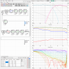
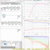
I made a couple XO's with the data to monkey with the verticals a bit just to show what I mean. I have no clue if I can cross as low as I did.

I guess another way of phrasing my question is, would you give up a few db of power and DI for less of a drop in the vertical directivity? The newbie part of me wants to make all of the graphs look in balance without knowing the importance of each.

To help see things, only the 0-30, and 90 degrees vertical is displayed in the polar window. The OG image is the XO you made.
 

Attachments

  • v12c_edit Six-pack_OG.png
    v12c_edit Six-pack_OG.png
    99.6 KB · Views: 214
  • v12c_edit Six-pack_r2.png
    v12c_edit Six-pack_r2.png
    99 KB · Views: 201
  • v12c_edit Six-pack_r4.png
    v12c_edit Six-pack_r4.png
    98.7 KB · Views: 187

Trdat

Addicted to Fun and Learning
Forum Donor
Joined
Sep 6, 2019
Messages
968
Likes
397
Location
Yerevan "Sydney Born"
But you are asking about the midrange, and for the small midrange drivers you identified, about 2", the crossover point will likely be high enough such that baffle edge diffraction will be a concern for the midrange. The lowest frequency where baffle edge diffraction occurs is where the wavelength is twice the longer distance, from the driver center to the edge. So, for example, if the baffle is 12" wide and the driver in question is 4" from one edge and 8" from the other, the longer distance will be 8", [EDIT: the corresponding full wavelength will be 16", which corresponds to about 850 Hz], which would certainly fall within the range of most any midrange driver. .

Can you give us a simple equation? The corresponding full wavelenght will be 16'' which corresponds to about 850hz, this part I can't workout. Essentially your rule helps figure out if the midrange will be effected by baffle difraction?

I mean for arguments sake we can't use a waveguide on the midrange. And we have accounted for the general lobing using 1.4 times wavelenght at XO and the XO will be around 2700hz or 2800 maybe even 2900hz. What I am trying to achieve a narrow baffle?

Also, I am curious about how baffle edge diffraction is mitigated in a speaker that is layed vertically. If you look in my profile photo top right corner I have a 3 way, it is a trusted design by a trusted deisgner but am curious if by looking at it the side which has the 8inch woofer has a baffle edge far enough to mitigate the issue(as mentioned in your other post)? And I am presuming that the other side(to the side of the tweter and midrange to the baffle) is also narrow enough?
 

dorirod

Active Member
Joined
Oct 9, 2019
Messages
252
Likes
254
Here is a look for those who do not have VituixCAD installed,,,

Thanks for sharing all these details. I don't know anything about XO desgin, but I'm curious what does that last PEQ filter on the tweeter do with a 0.1dB amplitude? It seems rather small, but I'm probably missing something obvious.
 
OP
Rick Sykora

Rick Sykora

Major Contributor
Forum Donor
Joined
Jan 14, 2020
Messages
3,613
Likes
7,344
Location
Stow, Ohio USA
Thanks for sharing all these details. I don't know anything about XO desgin, but I'm curious what does that last PEQ filter on the tweeter do with a 0.1dB amplitude? It seems rather small, but I'm probably missing something obvious.

Since it is @ctrl design and rather not speculate, will have to wait for him to answer...
 

ctrl

Major Contributor
Forum Donor
Joined
Jan 24, 2020
Messages
1,633
Likes
6,240
Location
.de, DE, DEU
How much stock do you put into adjusting the vertical directivity in the XO? Or does everything else matter more?
Interesting question. I guess everyone has their own personal opinion on that. I am not aware of any study that systematically deals with this issue.

If it's not a near-field monitor, I'm willing to accept a significant compromise in the vertical radiation. Stronger dips are okay, humps are to be avoided.

Funnily enough, the vertical frequency response measurements of a loudspeaker, which, according to my auditory perception, does not change its timbre at all (almost not), regardless of whether one is sitting, standing or walking towards the loudspeaker, look like this:

1619633413241.png 1619633444627.png
This is an M-M-T arrangement. The idea behind it is based on my experience with pseudo D'Appolito speakers (M-T-M), which also often show little change in timbre in the vertical direction.

To control the midrange vertically even more, I use the M-M-T arrangement and accept strong narrowband dips for it.
Due to the fact that the tweeter is located at the upper edge of the speaker cabinet, the radiation in the high frequency is extremely even upwards.
If you ignore the dips, the result is a uniform vertical radiation with a "reduced" upper midrange and slightly rising treble - something that even a coaxial design cannot achieve in this way.

As others here in the forum have often pointed out, there is still a lot of research to be done regarding the vertical radiation of loudspeakers and their pyschoacoustic effect.


...but I'm curious what does that last PEQ filter on the tweeter do with a 0.1dB amplitude? It seems rather small, but I'm probably missing something obvious.
Since it is @ctrl design and rather not speculate, will have to wait for him to answer...
You don't know that, that's the secret audiophile ingredient ;)

This is simply a leftover, instead of deleting it I usually set the component to "short" to bypass it, which I forgot to do in this case.
A human error so to speak, we can all be glad that my hobby is not nuclear power plant construction.
 

MZKM

Major Contributor
Forum Donor
Joined
Dec 1, 2018
Messages
4,250
Likes
11,556
Location
Land O’ Lakes, FL
Here is a look for those who do not have VituixCAD installed,,,

View attachment 126738
The individual curves look pretty great.
However:
The Sound Power is 5dB at ~650Hz?
That is a pretty narrow directivity, thought it would be wider as the Purifi doesn't beam that low. Then there is also the lowering in DI above 4500Hz.
 
Last edited:
OP
Rick Sykora

Rick Sykora

Major Contributor
Forum Donor
Joined
Jan 14, 2020
Messages
3,613
Likes
7,344
Location
Stow, Ohio USA
The individual curves look pretty great.
However:
The Sound Power is 5dB at ~650Hz?
That is a pretty narrow directivity, thought it would be wider as the Purifi doesn't beam that low. Then there is also the lowering in DI above 4500Hz.

Thought we had posted something earlier, but could not find...

I thought @ctrl said the directivity of the rectangular cabinet would suffer over 5k Hz compared to the truncated pyramid cabinet. As the complexity of the pyramid design was more than I preferred initially, I decided to start with the simpler design. Will check with him but grabbing some dinner now. ;)
 

ctrl

Major Contributor
Forum Donor
Joined
Jan 24, 2020
Messages
1,633
Likes
6,240
Location
.de, DE, DEU
Had to realize that in the simulations of the Seas-DXT the TSP values were not correct (makes a little difference). Therefore at this point again the VCAD projects for the simulated frequency responses.

In VCAD the frequency response should be set to 200-18000Hz in the settings. These are the outermost limits of the simulation.

On axis the frequency response of the Seas-DXT should be valid up to about 7-8kHz, with angles >40° up to about 12kHz (with about +-1dB error deviation). This also means that DI or sound power are only reasonably reliable up to about 7-8kHz.
The real measurements will of course be more "fidgety", especially if they are measured with the NFS.

UPDATE: The virtual microphone was located at a distance of 2m during the simulations, exactly between the tweeter and woofer.

So if you want to "play" a bit with the two versions, attached are the two simulated projects.

Directiva-Stock (v12c.zip)
1619644676124.png

Directiva-Custom (v17a_22mm.zip)
1619644690137.png

First image is always Directiva-Stock, second Directiva-Custom.
With a crossover from [email protected], the differences between the two versions are minor.
1619645688819.png 1619645715541.png

However, if the crossover frequency is chosen low (in commercial loudspeakers the Seas-DXT is used down to 1250Hz), the differences in horizontal directivity are significant.
1619645963786.png 1619645984151.png
1619646108114.png 1619646125934.png
 

Attachments

  • v12c.zip
    395.2 KB · Views: 104
  • v17a_22mm.zip
    393.9 KB · Views: 83
Last edited:
OP
Rick Sykora

Rick Sykora

Major Contributor
Forum Donor
Joined
Jan 14, 2020
Messages
3,613
Likes
7,344
Location
Stow, Ohio USA
[QUOTE="ctrl, post: 763250, member: 12723"
You don't know that, that's the secret audiophile ingredient ;)

This is simply a leftover, instead of deleting it I usually set the component to "short" to bypass it, which I forgot to do in this case.
A human error so to speak, we can all be glad that my hobby is not nuclear power plant construction.[/QUOTE]

I know now. :D

I did short it and saw that it had no visible effect, but I tend to be minimalistic and so just wanted to be sure this just wasn't a difference in style.
 

MrPeabody

Addicted to Fun and Learning
Joined
Dec 19, 2020
Messages
657
Likes
945
Location
USA
Can you give us a simple equation? The corresponding full wavelenght will be 16'' which corresponds to about 850hz, this part I can't workout. Essentially your rule helps figure out if the midrange will be effected by baffle difraction?

I mean for arguments sake we can't use a waveguide on the midrange. And we have accounted for the general lobing using 1.4 times wavelenght at XO and the XO will be around 2700hz or 2800 maybe even 2900hz. What I am trying to achieve a narrow baffle?

Also, I am curious about how baffle edge diffraction is mitigated in a speaker that is layed vertically. If you look in my profile photo top right corner I have a 3 way, it is a trusted design by a trusted deisgner but am curious if by looking at it the side which has the 8inch woofer has a baffle edge far enough to mitigate the issue(as mentioned in your other post)? And I am presuming that the other side(to the side of the tweter and midrange to the baffle) is also narrow enough?

You ask good questions, and I wish I could give equally good answers to all, but I'm not sure. You want a simple formula of some sort, but I'm not sure this is reasonable because of the gradual nature of the effect. What I can do is have a try at a better explanation, although this is clearly not what you want. Sitting here at the keyboard I started typing and ended up with something much longer than I had intended to write. (This always happens to me.) Should I delete it, or should I go ahead and post it? It might be helpful to you, and it isn't going to do any harm.

A good source of information on this topic is found in Linkwitz' general discussion of speaker design. Last I checked it is still found in the website that is still being maintained. One section of that broad discussion of speaker design is devoted to baffle edge diffraction. He did a bunch of experiments with tweeters mounted on simple baffles of various size, set on a tall pole. His experiments echoed earlier experiments done by Harry F. Olson. Speaking of Olson, his two major books on acoustics are now available for free on line, and therein you will find his experiments and conclusions on baffle edge diffraction and the effect of the shape of the enclosure. Somewhere on the ASR site there is a list of recommended reference material, and somewhere toward the end of it, you should find links to online locations where you can grab copies of Olson's books. If you want.

Before I go any further I also need to apologize to Rick and ctrl for dumping this in their Directiva thread. They've both been very generous to people who've taken the thread off on divergent paths. If there is ever a cleanup of the Directiva thread, maybe this post could be moved somewhere else.

Baffle edge diffraction is intimately related to the baffle step effect. Usually these two phenomena are thought of as separate phenomena, but they cannot be cleanly separated. As concerns the baffle step, we know that at adequately high frequency, where the wavelength is much shorter than the baffle dimensions, the radiation is into hemispherical space. This implies +6 dB of gain (for the area directly in front of the speaker) vs. low frequency. For a perfectly spherical speaker we would expect a very smooth, gradual step increase from low to high frequency, amounting to +6 dB overall, with the bulk of it occurring within a spread of just a few octaves. At wavelength much greater than the biggest dimension of the speaker and baffle, the wave envelopes the speaker and pays no heed to whether the speaker enclosure is spherical or rectangular or whatever, because the irregularities of the speaker enclosure are dimensionally small in comparison to the wavelength. As frequency increases and the wavelength shortens, eventually the wavelength is short enough such that the irregularities of the speaker enclosure are no longer dimensionally small in comparison to the wavelength.

When the wave emitted by the driver reaches the edge of the baffle there is an abrupt decrease in acoustic impedance. A secondary wave propagates from the baffle edge (all along the baffle edge, all the way around). When an abrupt change in acoustic impedance is a decrease, the wave propagating from the point of diffraction is shifted by 180 degrees relative to the incident wave. This is one of two sources of phase offset, for the diffracted wave relative to the wave reaching the listener directly from the driver. The other source of phase offset is the difference in the two distances: the distance from the listener directly to the driver center, vs. the longer, indirect distance that takes a detour. For a listener on-axis the distance to the edge where diffraction occurs is approximately the same as the distance from the listener to the center of the driver. Thus, the difference in the two distances is approximately the distance from the center of the driver to the edge of the baffle. The amount of phase shift that this distance implies depends on how great this distance is in relation to the wavelength. And to this amount of phase shift, you add the other 180 degrees, to obtain the full phase offset for the diffracted wave.

At very low frequency where the wavelength is very long compared to the baffle dimensions, the amount of phase shift associated with the distance from the center of the driver to the baffle edge will be very close to 0, which means that the total phase shift will be the 180 degrees associated with the soft reflection. 180 degrees of phase shift implies mutual (partial) annihilation; the -6 dB baffle step loss can be explained by way of the phase cancellation.

As frequency increases and wavelength shortens, the distance from the center of the driver to the baffle edge becomes an increasingly greater fraction of the wavelength. The amount of associated phase shift increases from 0 degrees to something bigger than 0, eventually to 180, such that the total phase shift gradually migrates from 180 degrees to 360 degrees (or to 0 degrees, as you prefer to think of it). Since the phase cancellation effect decreases in strength, the response rises (i.e., the step). Eventually, the distance from the center of the driver to the baffle edge (the greatest of the several baffle edge distances) will be half of the wavelength. At this point each of the two sources of phase shift contributes 180 degrees, which that the total phase shift is 180 + 180 = 360. This of course means reinforcement rather than cancellation. At this wavelength, there is a prominent hump superimposed on the erstwhile smooth baffle step. This hump is located at wavelength equal to twice the distance from the center of the driver to the baffle edge. (More specifically, the baffle edge furthest from the driver.)

With many speakers, tall/skinny speakers in particular, the distance along that furthest edge of the baffle will be significantly shorter than the baffle edges that are nearer the driver. It is nevertheless useful to examine the special case where the baffle is perfectly square and the driver is located at the center of the baffle. In this case, the full wavelength, being equal to twice the half-wavelength, is equal to the width of the baffle. Thus, all we need to do, to obtain the corresponding frequency, is to take wavelength equal to the baffle width and translate this to frequency. For anyone who has any difficultly remembering how to do this, it can be helpful to think about the units. Since frequency is expressed in reciprocal seconds, it is apparent that you divide the speed of sound (which is expressed in units of distance divided by time, i.e., 1125 ft/s), by wavelength, which is expressed in units of distance. The distance units cancel and you are left with reciprocal seconds. For example, if the baffle width is 1 ft, you divide 1125 ft/s by 1 ft and get 1125 reciprocal seconds, i.e., 1125 Hz. This is the frequency at which the prominent first hump in the diffraction ripple is found, for a 12" x 12" baffle with driver mounted at the center.

As the frequency increases further and the wavelength shortens further, eventually the distance from the center of the driver to the baffle edge will equal a full wavelength. At this point in frequency the total phase difference will be 180 degrees, which means that instead of a peak, there will be a dip. For the square 12"x12" baffle this occurs at 2250 Hz. Then another peak at 3 x 1125 Hz, and another dip at 4 x 1125 Hz, etc.

Mr. Linkwitz subtly suggested making the baffle 2x or 4x or even 8x greater in one dimension vs. the other, and locating the driver 1/3 of the way from one edge, for both the vertical and horizontal dimensions. This leads to mutual cancellation among the dips and peaks in the different ripples associated with the different edges, sort of. This isn't a complete solution, for two reasons. One reason is that this mutual cancellation effect only works for listening positions directly on axis. For off-axis listening positions it doesn't work, because the phase relationships get out of whack. The other reason is that there isn't any dip anywhere that would cancel with the prominent first peak. If the driver is located 1/3 of the way from one of the side edges, the first peak associated with the shorter distance will coincide in frequency with the first dip associated with the longer distance. Still, there will be some suppression of that strong first peak, owing to the fact that only one edge is generating that prominent first peak, rather than both acting in unison. For a tall skinny speaker with rectangular baffle in the 4:1 or 8:1 ratio, the prominent first peak will most likely be suppressed adequately by a combination of other effects, including the effect whereby sound intensity weakens with increasing distance from the source. Still, it should be remembered that the mutual cancellation effect works only for listeners directly on axis. As you move off-axis in any direction, the phase relationships change in a way that is theoretically predictable yet chaotic for intents and purposes.

The question of how you know which drivers are affected is not an easy question. In order for a driver to not be affected, the upper limit of its frequency band needs to be an octave or so lower than the calculated frequency of the first peak in the ripple, using the greatest driver-center-to-baffle-edge distance. In general it is not necessary to completely avoid this effect. It is desirable to avoid this effect to the extent that is practical, and it is up to the individual speaker designer to decide what "practical" means. This effect is one among a slew of reasons why real speakers cannot achieve perfection. One of the best mitigating strategies is the use of strong beveling, where the bevel surfaces are nearly as prominent as the baffle itself, such that the enclosure is a crude approximation of a sphere, a tall cylinder, or cone, or some hybrid of these shapes.
 

headshake

Active Member
Joined
Apr 20, 2019
Messages
297
Likes
238
Interesting question. I guess everyone has their own personal opinion on that. I am not aware of any study that systematically deals with this issue.

If it's not a near-field monitor, I'm willing to accept a significant compromise in the vertical radiation. Stronger dips are okay, humps are to be avoided.

Funnily enough, the vertical frequency response measurements of a loudspeaker, which, according to my auditory perception, does not change its timbre at all (almost not), regardless of whether one is sitting, standing or walking towards the loudspeaker, look like this:

View attachment 126907 View attachment 126908
This is an M-M-T arrangement. The idea behind it is based on my experience with pseudo D'Appolito speakers (M-T-M), which also often show little change in timbre in the vertical direction.

To control the midrange vertically even more, I use the M-M-T arrangement and accept strong narrowband dips for it.
Due to the fact that the tweeter is located at the upper edge of the speaker cabinet, the radiation in the high frequency is extremely even upwards.
If you ignore the dips, the result is a uniform vertical radiation with a "reduced" upper midrange and slightly rising treble - something that even a coaxial design cannot achieve in this way.

As others here in the forum have often pointed out, there is still a lot of research to be done regarding the vertical radiation of loudspeakers and their pyschoacoustic effect..

Thanks for writing all that up. It is neat to see these design choices and read the "why" of them.

I took a look at the horizontal views of the same XO's as my prev post that adjusted for the vertical. Anything above 75db is carved out to highlight the differences. The r2 XO is probably impossible, the OG is yours, and the r4 XO is just a little lower than yours. So there is a little difference in the horizontal off-axis 2khz-10khz if the vert is adjusted at the cost of the DI graph not looking as nice. Ok, now I get the tradeoffs.
 

Attachments

  • v12c_edit Directivity (hor)_r2.png
    v12c_edit Directivity (hor)_r2.png
    126.5 KB · Views: 103
  • v12c_edit Directivity (hor)_r4.png
    v12c_edit Directivity (hor)_r4.png
    132.9 KB · Views: 102
  • v12c_edit Directivity (hor)OG.png
    v12c_edit Directivity (hor)OG.png
    137 KB · Views: 100
OP
Rick Sykora

Rick Sykora

Major Contributor
Forum Donor
Joined
Jan 14, 2020
Messages
3,613
Likes
7,344
Location
Stow, Ohio USA
So, we move on to the next phase for Directiva. Amir will make measurements and we will create a crossover based on them.

In the meanwhile, should explain more about the current VCAD project. While it is a usable directivity model, it is not one that can be loaded into a minidsp unmodified. This is because the directivity sims used for the driver frequency responses do not fully represent the output capabilities of the drivers relative to each other. Notably, the woofer has much lower SPL than in the VCAD model. This will be corrected once Amir makes his measurements.

Am working to pack up and ship the speaker to Amir. It should ship on Monday. :cool:
 

tktran303

Addicted to Fun and Learning
Forum Donor
Joined
Mar 27, 2019
Messages
685
Likes
1,199
Will Amir measure individual driver units sans crossover?

Or with the crossover in place, and then you’ll use that to make iterative changes?
 
OP
Rick Sykora

Rick Sykora

Major Contributor
Forum Donor
Joined
Jan 14, 2020
Messages
3,613
Likes
7,344
Location
Stow, Ohio USA
Will Amir measure individual driver units sans crossover?

Or with the crossover in place, and then you’ll use that to make iterative changes?

Originally, thought the latter, but sans crossover seems cleaner, so that is the plan.
 

Trdat

Addicted to Fun and Learning
Forum Donor
Joined
Sep 6, 2019
Messages
968
Likes
397
Location
Yerevan "Sydney Born"
You ask good questions, and I wish I could give equally good answers to all, but I'm not sure. You want a simple formula of some sort, but I'm not sure this is reasonable because of the gradual nature of the effect. What I can do is have a try at a better explanation, although this is clearly not what you want. Sitting here at the keyboard I started typing and ended up with something much longer than I had intended to write. (This always happens to me.) Should I delete it, or should I go ahead and post it? It might be helpful to you, and it isn't going to do any harm.
.

You did good to post it. I am just trying to get my head around it, and it will take time. So let me absorb what I can and come back with questions. If need be we can put in another thread but I think the whole point is to make threads like this educational on speaker design. But if they want to move it no problem.
 
OP
Rick Sykora

Rick Sykora

Major Contributor
Forum Donor
Joined
Jan 14, 2020
Messages
3,613
Likes
7,344
Location
Stow, Ohio USA
You did good to post it. I am just trying to get my head around it, and it will take time. So let me absorb what I can and come back with questions. If need be we can put in another thread but I think the whole point is to make threads like this educational on speaker design. But if they want to move it no problem.

The advantage of a new thread is not only avoiding the off-topic aspect, but also allows others to more readily find the new topic...;););)
 

Trdat

Addicted to Fun and Learning
Forum Donor
Joined
Sep 6, 2019
Messages
968
Likes
397
Location
Yerevan "Sydney Born"
The advantage of a new thread is not only avoiding the off-topic aspect, but also allows others to more readily find the new topic...;););)

Yeh like pointless back and forths like this one. Lol! I am sure BDWoody will chime in and work it out. But yeh lets keep this thread consice and keep the valuable information unrelated somwhere easy to be found.
 

MrPeabody

Addicted to Fun and Learning
Joined
Dec 19, 2020
Messages
657
Likes
945
Location
USA
Just thought that I would quickly mention that we have a new member @René - Acculution.com who is doing simulation studies and has indicated that we can look forward to studies of baffle edge diffraction. I posted a comment to his thread and mentioned that @ctrl is similarly engaged in simulation studies and has produced some interesting and useful results on ASR. When Dr. Rene's study of baffle edge diffraction arrives, there will no doubt be lots of discussion of the topic, most likely on a thread dedicated to his simulation studies, possibly on a thread dedicated to just the study of baffle edge diffraction. Definitely something to look forward to.

MEANWHILE, we continue to look forward to seeing Amir's measurements if they are shared, or to the final measurements after the crossover design has been finalized and implemented. It is with the crossover where the speaker designer is never quite sure when the creation is finished. The same problem for the artist who paints a painting. Am I done with it? Maybe. When the artist signs the painting, this is how you know when he is finished. The speaker builder who builds for his personal use does not sign the speaker, and is thus never sure when he has finished until it has faded so far into the past that he can no longer recall what the crossover topology looked like. I am looking forward to seeing the crossover design that Rick and ctrl agree to use with this speaker!
 
Top Bottom