• Welcome to ASR. There are many reviews of audio hardware and expert members to help answer your questions. Click here to have your audio equipment measured for free!

Inexpensive Automated Speaker Measurements: Using an Off-the-Shelf Motorized Turntable for CEA-2034 Spinorama

ObjectAudio

Member
Joined
Jan 22, 2021
Messages
74
Likes
136
I wanted to share a project I’ve been working on to simplify CTA-2034 / Spinorama measurements at home without spending thousands on dedicated hardware.

I adapted a low-cost, programmable motorized photography turntable to handle automated angular positioning. It can be controlled via USB using script commands. I’m currently using it with my own custom software, but it could easily be adapted to work with other existing software tools.

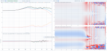
Attached is a screenshot of a Spinorama capture mid-process.

For reference, here is the link to the product: https://www.amazon.com/dp/B0FBX2NXX6?ref=ppx_yo2ov_dt_b_fed_asin_title&th=1

I decided to go with the 15.8" model, which is a bit more expensive, but the 12.6" version should be more than sufficient for lighter-duty measurements.
1789334279786.png
 
What a great idea! Not cheap, but perfectly suited to the task.
 
It could certainly be done using REW or ARTA, but it would require some additional custom software development. If I get some free time, I'll look into it to see how feasible that would be. However, with either of those solutions, you would still need VituixCAD to process the measurements and generate the final CEA-2034 / Spinorama plots. My software handles the entire workflow—from turntable control and measurement capture to generating the CEA-2034 results—all in one application
1789385245030.png
 
It could certainly be done using REW or ARTA, but it would require some additional custom software development. If I get some free time, I'll look into it to see how feasible that would be. However, with either of those solutions, you would still need VituixCAD to process the measurements and generate the final CEA-2034 / Spinorama plots. My software handles the entire workflow—from turntable control and measurement capture to generating the CEA-2034 results—all in one applicationView attachment 558706

Is this software something you plan to share/publish? I'd be interested to buy the turntable and test the software.
 
Yes, plus the ability to design EQ filters for the on-axis response, listening window, or estimated in-room response (PIR).
 
I developed a driver for ARTA, which I will release to the community in the next few days. I will also work on a driver for REW, but it looks like that requires the Pro version.
 
No plans to release the full app right now—as it's part of a much broader software project I'm working on. That's why I intend to release the ARTA driver (and work on REW integration) so others can automate the turntable with tools they already use.
 
This is a really clever idea, and hats off for sharing it with the community to play with while you continue to work on your software.
 
Quick Update: I ended up replacing the 15.8" top plate with a 19.7" version and bought this stand on Amazon. It fits perfectly end-to-end with a wide, stable base, making it easy to center the rig on the rotation axis.

For anyone who has done Spinorama measurements, the main challenge is that the standard recommends placing the speaker's front baffle directly on the rotation axis. This creates mounting and weight distribution issues—especially during vertical directivity testing when laying the speaker on its side (where the tweeter is usually off-axis).

My software solves this issue by mathematically modeling the rotation axis to remain centered on the enclosure, even for vertical sweeps. I think this makes CTA-2034 Spinorama measurements so much easier and more accessible to everyone. Combined with this hardware setup, I think this approach makes capturing detailed, high-resolution CTA-2034 data far more accessible and hassle-free for DIY builders.
 
They've got quite a lot of documentation about how to control it. Start at https://comxim.com/development-kit/ - it's taking text based commands via USB serial port or network socket. I've not checked the bluetooth, but it's probably similar. It's a lot easier than the REW API so if you can automate REW the platform rotation should be easy. It seems like an excellent off the shelf solution.
 
I mentioned that my software allows the speaker's cabinet to be centered on the turntable axis instead of the front baffle, and mathematically corrects the result to what CTA-2034 specifies. The question is how large the errors of the centered setup actually are, and how completely they can be removed. I have now built a controlled simulation to test exactly that, and this post summarizes the method and results.

The Problem CTA-2034 defines rotation about the speaker's reference point, which is typically the tweeter on the front baffle. On a physical turntable, this places the entire cabinet behind the platter's center—an impractical arrangement for heavy speakers, and particularly awkward for vertical sweeps where the speaker lies on its side.

The usual practice is to center the cabinet on the platter. The front baffle then sits half the cabinet depth in front of the rotation axis. As a result, the microphone is closer than nominal on-axis and farther away at the sides, meaning each angle is recorded from a slightly different distance and direction than intended. The question is how much this affects the CTA-2034 curves, and whether those errors can be corrected in software.

Method measured physical speaker cannot serve as a reference here, because its true CTA-2034 response isn't known independently of the measurement itself. The software therefore simulates an ideal speaker: a two-way system (6.5" woofer, 1" dome tweeter in a 22 x 38 x 28 cm sealed box, 4th-order LR crossover at 2 kHz, including cabinet edge diffraction, with the mic at 1 m).

Because the speaker is simulated, it can be spun twice:

  1. Reference Run: Rotated around the front baffle (yielding the exact CTA-2034 standard).
  2. Centered Run: Rotated around the cabinet's middle (yielding what a physical turntable actually records).
The difference between the two isolates the error of the centered setup with zero external noise.


The centered rig modeled upright for horizontal sweeps, and on its side for vertical sweeps, with the platter's axis passing through the
CEA-2034 Ver.png

1789836366852.png


middle of the cabinet and the mic aimed at that axis.
Mid-Hor.png


  • Mid-Ver.png
    Cabinnet Mid.png
Results Without Correction Comparing the uncorrected centered spin with the reference :

  • Level Shift: Every curve reads above the reference, but by varying amounts: On-Axis is about +1.3 dB high, Listening Window is +1.2 dB, Early Reflections is +0.7 dB, and Sound Power is near 0 dB in the bass, rising to +0.4 dB at high frequencies. The mic is 14 cm closer on-axis than at the sides, and the curves directly reflect that geometry.
  • Directivity Index (DI) Error: Because the offsets vary between curves, the Directivity Index reads about 0.85 dB too high across all frequencies. This is the main takeaway: an uncorrected centered spin makes the speaker appear significantly more directional than it actually is.
  • Bass Artifacts: The difference map is uniformly blue ("quieter off-axis than reference") across all frequencies, including 100 Hz where a box of this size is omnidirectional. A spinorama that shows directivity at 100 Hz was not rotated about its reference point—a useful sanity check for any measurement rig.
  • Summary: Mean level is 0.77 dB high, and the worst curve deviates by 1.13 dB RMS in shape.


Cabinnet Mid-corr.png


Results With Correction Applying the correction:
  • Level Error: Reduced from 0.77 dB -> 0.05 dB.
  • Shape Error (Worst Curve): Reduced from 1.13 dB -> 0.11 dB RMS.
  • DI & Difference Map: The Directivity Index error is eliminated, and the difference map flattens to near-neutral.
Residual Errors The remaining residual is small and comes from two identifiable sources:
  1. Crossover Dip (~0.2 dB between 1.5–3 kHz): The two drivers are 190 mm apart, and their path difference to the mic differs slightly at 0.86 m vs 1 m. A single geometric reference point cannot resolve driver spacing.
  2. On-Axis Ripple (+/- 0.3 dB above 3 kHz): Caused by the cabinet's edge-diffraction pattern shifting marginally with distance (~1 mm rim path shift, or 8 degrees of phase shift at 8 kHz).
Importantly, the averaged curves (Listening Window, Early Reflections, Sound Power) smooth these out and remain within about 0.1 dB. Both residuals cut roughly in half if measured at a 2 m distance.

Summary & Takeaway

The bottom line is very encouraging for DIY measurement rigs.

A corrected 1 m spin with the cabinet centered lands within ~0.1 dB of the true CTA-2034 reference on averaged curves. That puts its accuracy right on par with top-tier, multi-thousand-dollar commercial measurement systems, while keeping the physical hardware setup fast, stable, and straightforward.

You don't need awkward counterweights or unstable physical offsets to capture reliable polar data. Simple software geometry does the heavy lifting, bringing high-end Spinorama precision within easy reach of any DIY setup.

 

Attachments

  • Cabinnet Mid-corr.png
    Cabinnet Mid-corr.png
    659.3 KB · Views: 36
The Problem CTA-2034 defines rotation about the speaker's reference point, which is typically the tweeter on the front baffle. On a physical turntable, this places the entire cabinet behind the platter's center—an impractical arrangement for heavy speakers, and particularly awkward for vertical sweeps where the speaker lies on its side.
If someone is serious about building DIY speakers and taking spinorama measurements these things are not difficult to address. There are pictures of turntables that are quite easy to build that handle this easily here on ASR and at diyAudio.com.
 
If someone is serious about building DIY speakers and taking spinorama measurements these things are not difficult to address. There are pictures of turntables that are quite easy to build that handle this easily here on ASR and at diyAudio.com.
Building a custom physical jig is certainly possible, but it misses the entire point of this thread: leveraging a low-cost, off-the-shelf USB motorized turntable for maximum convenience and safety.

Cantilevered physical setups create severe weight distribution and stability issues—especially when mounting heavier speakers or lying them on their side for vertical sweeps. Off-center loads place significant bending torque on standard turntable bearings and motors.

Centering the cabinet keeps the center of gravity stable, protects the hardware, and takes seconds to set up. Letting software handle the geometry correction down to ~0.1 dB accuracy gives you high-precision CTA-2034 data with zero mechanical hassle.
 
Quick Update: I ended up replacing the 15.8" top plate with a 19.7" version and bought this stand on Amazon. It fits perfectly end-to-end with a wide, stable base, making it easy to center the rig on the rotation axis.
So, how is the quality of ComXim programmable turntables? Do they work as you had hoped, or have you run into any issues? If these work well, I'm pretty sure I will get one.
 
@ObjectAudio It seems a bit strange to me that the CTA2034 standard suggests such an impractical way to measure (not having the speaker centered on the platter).

Looking at Erin's videos he doesn't seem to place the speaker off-center, and I don't think Amir does either. Does the Klippel NFS software have this type of correction too?
 
How can you not afford a klippel my dude with how expensive your speakers are?

They're not expensive. But they are out of budget for many people. Luckily there are good products in all price categories these days.
 
Back
Top Bottom