Simulation and documented successful practical using of porous treatment in a room in areas of high sound pressure. Which treatment is prohibited or not recommended by someone somewhere on YouTube.the things you shared had anything to do with what I said?

-
WANTED: Happy members who like to discuss audio and other topics related to our interest. Desire to learn and share knowledge of science required. There are many reviews of audio hardware and expert members to help answer your questions. Click here to have your audio equipment measured for free!
You are using an out of date browser. It may not display this or other websites correctly.
You should upgrade or use an alternative browser.
You should upgrade or use an alternative browser.
In-Room Speaker Frequency Response Simulation (Low Frequency)
- Thread starter NTK
- Start date
these people are covering the whole bloody boundary, no shits given about whether it's high pressure or high velocity.Simulation and documented successful practical using of porous treatment in a room in areas of high sound pressure. Which treatment is prohibited or not recommended by someone somewhere on YouTube.
OP
- Thread Starter
- #64
When you have a standing wave (i.e. room modes), the areas with the pressure maxima are also the areas with the velocity minima, and vice versa. Therefore, to dissipate the energy by placing porous/lossy media in the room, which works by adding frictional resistance to the oscillating movement of the "acoustic particles", the most effective locations will be where the acoustic particles move a lot -- where the velocity maxima (and pressure minima) are. And, similarly, the least effective locations will be where the pressure maxima/velocity minima are.Hey guys, I heard somewhere on YouTube that you should add porous treatment in a room in areas of high velocity and not in areas of high sound pressure.
Is this true? and is it something we can simulate?
At the wall, the acoustic particle velocity has to be the same as the velocity of the wall, which for a rigid wall is zero. Thus, at the wall, we have velocity minimum and pressure maximum, and thin porous absorbers installed on the walls aren't very useful.
This is also the reason why for anechoic chambers, the low frequency limit is determined by the protruded length of the wedges having to be more than 1/4 the wavelength of the low frequency limit. If you have zero velocity at the base, 1/4 wavelength away will correspond to the velocity maximum.
Picture source
mwmkravchenko
Active Member
More proof that much of what is on the internet is repeated rubbish. NTK and Flaesh have posted the truth.
Most room treatments especially the foam versions are so nearly useless when you are looking at the broadband nature of music. There is information available from a few manufactures regarding actual noise control. The ones that manufacture fibrous insulation, mineral wool and fiberglass wool in regards to building and ship sound suppression provide a relatively useful guide as to what their products can do in regards to noise absorption.
Most room treatments especially the foam versions are so nearly useless when you are looking at the broadband nature of music. There is information available from a few manufactures regarding actual noise control. The ones that manufacture fibrous insulation, mineral wool and fiberglass wool in regards to building and ship sound suppression provide a relatively useful guide as to what their products can do in regards to noise absorption.
Let's talk broadly about potential sources of errors in this simulation vs. reality. As usual I will restrict this discussion to low frequencies, i.e. below Schroeder (~300 Hz in typical rooms).
An obvious source of error is inaccuracies in the geometry: the size and shape of the room, and the position of the sources and receivers. We can safely assume that this error is negligible because it is trivial to minimize it: just pull out a laser measure and come up with a more accurate floorplan. The presence of furniture and various objects can arguably change the geometry of the room, but at low frequencies these are typically too small to matter much (especially at very low frequencies e.g. <100 Hz), where such objects can be assumed to be acoustically transparent.
Another source of errors is sound propagation loss in the air inside the room. For reasonable room sizes and at low frequencies these are negligible.
This leaves us with the most problematic, trickiest source of error: the acoustic behaviour of the boundaries, i.e. the walls, floor and ceiling of the room.
For a while I was struggling to find good sources of information on this topic, but recently I hit the mother lode: a vast array of research published in acoustics journals on precisely this topic, i.e. how to improve the modelling of room boundaries for the purposes of acoustic simulation, especially in small rooms and at low frequencies.
For those who want to dig deeper, here is my list of the most interesting papers I found (and their lists of references are usually full of great stuff too):
This paper explains how to go from absorption coefficient to surface impedance - it instantly answers some of the earlier questions in this thread (@NTK you might want to give that one a close read). Also, I now suspect the reason why there appears to be a discrepancy between the REW room simulator and the FEM simulator is because the latest FEM simulator code implicitly assumes the given absorption coefficient is for normal incidence, but (presumably) REW assumes random incidence. The linked paper explains that, due to the way the math works, one can go from one to the other simply by multiplying by a constant, which is consistent with our findings. For this reason I feel confident we can put that issue to bed. (But note that this only works under the local reaction assumption - more on that below. Both REW and the FEM simulator implicitly assume local reaction.)
From the above papers and others, I can try to come up with a summary of the boundary problems we have to tackle if we want to improve the accuracy of the simulation:
Using the same impedance for all boundaries. Obviously, real rooms use different kinds of boundaries for different walls, and the floor and ceiling. Using different parameters for each boundary would help, and that's a relatively trivial change that the FEM solver can easily accommodate.
Figuring out which parameters to use for a given type of boundary (e.g. carpet, suspended ceiling, drywall, etc.). Notably, this paper laments the poor state of material acoustical data available today, which is often ambiguous (e.g. "is this for normal or random incidence??"), obtained under questionable conditions, makes unstated assumptions, and come with reproducibility concerns.
The assumption that the absorption coefficient is constant across frequency is wrong in practice. Obviously most materials do not have the same absorption coefficient at 100 Hz as they would at 1000 Hz - we knew that already. But actually, it's worse than that in some cases. One particularly worrying problem is the common case of modern walls that are made of two layers of drywall separated by a gap (which is either filled with air, or some porous material like fiberglass). Incidentally, this is exactly what my own walls are made of. The problem is that two solid layers separated by a gap act as a mass-spring-mass system, which comes with a resonance frequency. Guess what: in the case of typical drywall constructions, the numbers conspire in such a way as to put the resonance frequency smack in the middle of the frequency range of interest (e.g. I calculated ~83 Hz for my own walls). Unsurprisingly, the wall tends to behave very differently around that resonance frequency. This paper studied this and found (via measurement) that the random absorption coefficient can go all the way from ~0.1 to ~0.4 around resonance - clearly this phenomenon cannot be ignored. My room also happens to have a suspended ceiling which I would expect to exhibit similar behaviour due to the air gap. Adding insult to injury, this paper suggests the resonance frequency is dependent on the angle of incidence (see in particular Figures 4.7-4.10), as discussed in my last point below.
The assumption that the normal surface impedance has no imaginary part. This paper suggests that at low frequencies this is more or less true regardless of the material, but notably this assumption breaks down at resonance (see previous point), where the imaginary part of the surface impedance varies rapidly and as a result the phase angle of the reflection coefficient tends to flip. This changes the phase of the reflected wave, which in turn affects the constructive/destructive interference patterns in the room, and therefore the frequency response at the receiver around the resonance frequency.
The assumption that the surface is locally reacting. This is the most fascinating and likely the most complex source of error. A surface is said to be locally reacting if its surface impedance stays the same regardless of the incidence angle. Note that this does not mean that its reflection/absorption coefficient stays the same regardless of the incidence angle. It clearly does not - in general, absorption is maximal at normal incidence, and virtually zero at grazing incidence (and I suspect the FEM solver already takes that into account implicitly). However, it does mean that this coefficient is a straightforward function of the incidence angle, which keeps things reasonably simple: if you know the normal surface impedance, then you can deduce the behaviour of a locally reacting surface for any angle of incidence. Apparently most acoustics simulation packages assume all surfaces are locally reacting, and I presume the same assumption is implicitly made in the Neumann boundary conditions used for solving PDEs like in FEM (if only because there is no way to specify the flux across a Neumann boundary as a function of incidence angle anyway).
Obviously the question that comes to mind is "is it reasonable to assume real world surfaces are locally reacting?". This paper studies precisely this question. The answer is yes for single layers of solid material (e.g. a single pane of glass). The answer is no for porous materials (e.g. fiberglass). And, most importantly (and unfortunately), the answer is no for walls made of multiple layers, such as a double layer of drywall with an air gap. This kind of surface exhibits "extended reaction" (the opposite of local reaction) due to the way sound is internally reflected by the various layers. At low frequencies, the main consequence is that the resonance frequency of the wall shifts with the incidence angle (see Figure 4.10), causing some error in the predicted frequency response (see Figure 5.5).
Now, it would appear that all of the above is fixable at least in theory. Obviously it's impractical to try to measure the impedance of the boundaries in the real world, but I believe it should still be possible, based on some basic construction data, to reconstruct a fairly accurate model of how the boundary behaves. For example, in the case of my walls, I know the thickness and density of the drywall panels on both sides, as well as the width and filling of the gap; from there it is possible to predict the resonance frequency, and from there the surface impedance, assuming local reaction. I haven't looked deeply into how the aforementioned paper came up with the extended reaction model for this case, but in theory it should be possible to retrace the steps (possibly with some difficult math). What's more worrying is that it's not clear how FEM can model extended reaction, i.e. a boundary whose impedance varies with the incidence angle. It could be that the easiest way to solve that problem is to forget about FEM entirely and instead use the technique described in the paper, called "phased beam tracing", which does take this into account.
One last potential source of error is "unknown unknowns", i.e. things that we don't even know about, or don't know how to quantify. One example could be the way drywall is mounted (i.e. the frame and studs), which restricts the movement (bending) of the wall. This paper measured real walls and therefore includes this effect, but papers that only use models (such as this one) don't.
An obvious source of error is inaccuracies in the geometry: the size and shape of the room, and the position of the sources and receivers. We can safely assume that this error is negligible because it is trivial to minimize it: just pull out a laser measure and come up with a more accurate floorplan. The presence of furniture and various objects can arguably change the geometry of the room, but at low frequencies these are typically too small to matter much (especially at very low frequencies e.g. <100 Hz), where such objects can be assumed to be acoustically transparent.
Another source of errors is sound propagation loss in the air inside the room. For reasonable room sizes and at low frequencies these are negligible.
This leaves us with the most problematic, trickiest source of error: the acoustic behaviour of the boundaries, i.e. the walls, floor and ceiling of the room.
For a while I was struggling to find good sources of information on this topic, but recently I hit the mother lode: a vast array of research published in acoustics journals on precisely this topic, i.e. how to improve the modelling of room boundaries for the purposes of acoustic simulation, especially in small rooms and at low frequencies.
For those who want to dig deeper, here is my list of the most interesting papers I found (and their lists of references are usually full of great stuff too):
- Uncertainty of input data for room acoustic simulations
- Acoustical modeling of rooms with extended-reaction surfaces
- Absorption and impedance boundary conditions for phased geometrical-acoustics methods
- Modelling the angle-dependent pressure reflection factor
- Sound Absorption of Gypsum Board Cavity Walls
This paper explains how to go from absorption coefficient to surface impedance - it instantly answers some of the earlier questions in this thread (@NTK you might want to give that one a close read). Also, I now suspect the reason why there appears to be a discrepancy between the REW room simulator and the FEM simulator is because the latest FEM simulator code implicitly assumes the given absorption coefficient is for normal incidence, but (presumably) REW assumes random incidence. The linked paper explains that, due to the way the math works, one can go from one to the other simply by multiplying by a constant, which is consistent with our findings. For this reason I feel confident we can put that issue to bed. (But note that this only works under the local reaction assumption - more on that below. Both REW and the FEM simulator implicitly assume local reaction.)
From the above papers and others, I can try to come up with a summary of the boundary problems we have to tackle if we want to improve the accuracy of the simulation:
Using the same impedance for all boundaries. Obviously, real rooms use different kinds of boundaries for different walls, and the floor and ceiling. Using different parameters for each boundary would help, and that's a relatively trivial change that the FEM solver can easily accommodate.
Figuring out which parameters to use for a given type of boundary (e.g. carpet, suspended ceiling, drywall, etc.). Notably, this paper laments the poor state of material acoustical data available today, which is often ambiguous (e.g. "is this for normal or random incidence??"), obtained under questionable conditions, makes unstated assumptions, and come with reproducibility concerns.
The assumption that the absorption coefficient is constant across frequency is wrong in practice. Obviously most materials do not have the same absorption coefficient at 100 Hz as they would at 1000 Hz - we knew that already. But actually, it's worse than that in some cases. One particularly worrying problem is the common case of modern walls that are made of two layers of drywall separated by a gap (which is either filled with air, or some porous material like fiberglass). Incidentally, this is exactly what my own walls are made of. The problem is that two solid layers separated by a gap act as a mass-spring-mass system, which comes with a resonance frequency. Guess what: in the case of typical drywall constructions, the numbers conspire in such a way as to put the resonance frequency smack in the middle of the frequency range of interest (e.g. I calculated ~83 Hz for my own walls). Unsurprisingly, the wall tends to behave very differently around that resonance frequency. This paper studied this and found (via measurement) that the random absorption coefficient can go all the way from ~0.1 to ~0.4 around resonance - clearly this phenomenon cannot be ignored. My room also happens to have a suspended ceiling which I would expect to exhibit similar behaviour due to the air gap. Adding insult to injury, this paper suggests the resonance frequency is dependent on the angle of incidence (see in particular Figures 4.7-4.10), as discussed in my last point below.
The assumption that the normal surface impedance has no imaginary part. This paper suggests that at low frequencies this is more or less true regardless of the material, but notably this assumption breaks down at resonance (see previous point), where the imaginary part of the surface impedance varies rapidly and as a result the phase angle of the reflection coefficient tends to flip. This changes the phase of the reflected wave, which in turn affects the constructive/destructive interference patterns in the room, and therefore the frequency response at the receiver around the resonance frequency.
The assumption that the surface is locally reacting. This is the most fascinating and likely the most complex source of error. A surface is said to be locally reacting if its surface impedance stays the same regardless of the incidence angle. Note that this does not mean that its reflection/absorption coefficient stays the same regardless of the incidence angle. It clearly does not - in general, absorption is maximal at normal incidence, and virtually zero at grazing incidence (and I suspect the FEM solver already takes that into account implicitly). However, it does mean that this coefficient is a straightforward function of the incidence angle, which keeps things reasonably simple: if you know the normal surface impedance, then you can deduce the behaviour of a locally reacting surface for any angle of incidence. Apparently most acoustics simulation packages assume all surfaces are locally reacting, and I presume the same assumption is implicitly made in the Neumann boundary conditions used for solving PDEs like in FEM (if only because there is no way to specify the flux across a Neumann boundary as a function of incidence angle anyway).
Obviously the question that comes to mind is "is it reasonable to assume real world surfaces are locally reacting?". This paper studies precisely this question. The answer is yes for single layers of solid material (e.g. a single pane of glass). The answer is no for porous materials (e.g. fiberglass). And, most importantly (and unfortunately), the answer is no for walls made of multiple layers, such as a double layer of drywall with an air gap. This kind of surface exhibits "extended reaction" (the opposite of local reaction) due to the way sound is internally reflected by the various layers. At low frequencies, the main consequence is that the resonance frequency of the wall shifts with the incidence angle (see Figure 4.10), causing some error in the predicted frequency response (see Figure 5.5).
Now, it would appear that all of the above is fixable at least in theory. Obviously it's impractical to try to measure the impedance of the boundaries in the real world, but I believe it should still be possible, based on some basic construction data, to reconstruct a fairly accurate model of how the boundary behaves. For example, in the case of my walls, I know the thickness and density of the drywall panels on both sides, as well as the width and filling of the gap; from there it is possible to predict the resonance frequency, and from there the surface impedance, assuming local reaction. I haven't looked deeply into how the aforementioned paper came up with the extended reaction model for this case, but in theory it should be possible to retrace the steps (possibly with some difficult math). What's more worrying is that it's not clear how FEM can model extended reaction, i.e. a boundary whose impedance varies with the incidence angle. It could be that the easiest way to solve that problem is to forget about FEM entirely and instead use the technique described in the paper, called "phased beam tracing", which does take this into account.
One last potential source of error is "unknown unknowns", i.e. things that we don't even know about, or don't know how to quantify. One example could be the way drywall is mounted (i.e. the frame and studs), which restricts the movement (bending) of the wall. This paper measured real walls and therefore includes this effect, but papers that only use models (such as this one) don't.
Last edited:
mwmkravchenko
Active Member
Thanks! I have a fair bit of reading to do now. Unfortunately some of these papers are behind pay walls.Let's talk broadly about potential sources of errors in this simulation vs. reality. As usual I will restrict this discussions to low frequencies, i.e. below Schroeder (~300 Hz in typical rooms).
An obvious source of error is inaccuracies in the geometry: the size and shape of the room, and the position of the sources and receivers. We can safely assume that this error is negligible because it is trivial to minimize it: just pull out a laser measure and come up with a more accurate floorplan. The presence of furniture and various objects can arguably change the geometry of the room, but at low frequencies these are typically too small to matter much (especially at very low frequencies e.g. <100 Hz), where such objects can be assumed to be acoustically transparent.
Another source of errors is sound propagation loss in the air inside the room. For reasonable room sizes and at low frequencies these are negligible.
This leaves us with the most problematic, trickiest source of error: the acoustic behaviour of the boundaries, i.e. the walls, floor and ceiling of the room.
For a while I was struggling to find good sources of information on this topic, but recently I hit the mother lode: a vast array of research published in acoustics journals on precisely this topic, i.e. how to improve the modelling of room boundaries for the purposes of acoustic simulation, especially in small rooms and at low frequencies.
For those who want to dig deeper, here is my list of the most interesting papers I found (and their lists of references are usually full of great stuff too):
- Uncertainty of input data for room acoustic simulations
- Acoustical modeling of rooms with extended-reaction surfaces
- Absorption and impedance boundary conditions for phased geometrical-acoustics methods
- Modelling the angle-dependent pressure reflection factor
- Sound Absorption of Gypsum Board Cavity Walls
This paper explains how to go from absorption coefficient to surface impedance - it instantly answers some of the earlier questions in this thread (@NTK you might want to give that one a close read). Also, I now suspect the reason why there appears to be a discrepancy between the REW room simulator and the FEM simulator is because the latest FEM simulator code implicitly assumes the given absorption coefficient is for normal incidence, but (presumably) REW assumes random incidence. The linked paper explains that, due to the way the math works, one can go from the other simply by multiplying by a constant, which is consistent with our findings. For this reason I feel confident we can put that issue to bed. (But note that this only works under the local reaction assumption - more on that below. Both REW and the FEM simulator implicitly assume local reaction.)
From the above papers and others, I can try to come up with a summary of the boundary problems we have to tackle if we want to improve the accuracy of the simulation:
Using the same impedance for all boundaries. Obviously, real rooms use different kinds of boundaries for different walls, and the floor and ceiling. Using different parameters for each boundary would help, and that's a relatively trivial change that the FEM solver can easily accommodate.
Figuring out which parameters to use for a given type of boundary (e.g. carpet, suspended ceiling, drywall, etc.). Notably, this paper laments the poor state of material acoustical data available today, which is often ambiguous (e.g. "is this for normal or random incidence??"), obtained under questionable conditions, makes unstated assumptions, and come with reproducibility concerns.
The assumption that the absorption coefficient is constant across frequency is wrong in practice. Obviously most materials do not have the same absorption coefficient at 100 Hz as they would at 1000 Hz - we knew that already. But actually, it's worse than that in some cases. One particularly worrying problem is the common case of modern walls that are made of two layers of drywall separated by a gap (which is either filled with air, or some porous material like fiberglass). Incidentally, this is exactly what my own walls are made of. The problem is that two solid layers separated by a gap act as a mass-spring-mass system, which comes with a resonance frequency. Guess what: in the case of typical drywall constructions, the numbers conspire in such a way as to put the resonance frequency smack in the middle of the frequency range of interest (e.g. I calculated ~83 Hz for my own walls). Unsurprisingly, the wall tends to behave very differently around that resonance frequency. This paper studied this and found (via measurement) that the random absorption coefficient can go all the way from ~0.1 to ~0.4 around resonance - clearly this phenomenon cannot be ignored. My room also happens to have a suspended ceiling which I would expect to exhibit similar behaviour due to the air gap. Adding insult to injury, this paper suggests the resonance frequency is dependent on the angle of incidence (see in particular Figures 4.7-4.10), as discussed in my last point below.
The assumption that the normal surface impedance has no imaginary part. This paper suggests that at low frequencies this is more or less true regardless of the material, but notably this assumption breaks down at resonance (see previous point), where the imaginary part of the surface impedance varies rapidly and as a result the phase angle of the reflection coefficient tends to flip. This changes the phase of the reflected wave, which in turn affects the constructive/destructive interference patterns in the room, and therefore the frequency response at the receiver around the resonance frequency.
The assumption that the surface is locally reacting. This is the most fascinating and likely the most complex source of error. A surface is said to be locally reacting if its surface impedance stays the same regardless of the incidence angle. Note that this does not mean that its reflection/absorption coefficient stays the same regardless of the incidence angle. It clearly does not - in general, absorption is maximal at normal incidence, and virtually zero at grazing incidence (and I suspect the FEM solver already takes that into account implicitly). However, it does mean that this coefficient is a straightforward function of the incidence angle, which keeps things reasonably simple: if you know the surface impedance, then you can deduce the behaviour of the surface for any angle of incidence. Apparently most acoustics simulation packages assume all surfaces are locally reacting, and I presume the same assumption is implicitly made in the Neumann boundary conditions used for solving PDEs like in FEM (if only because there is no way to specify the flux across a Neumann boundary as a function of incidence angle anyway).
Obviously the question that comes to mind is "is it reasonable to assume real world surfaces are locally reacting?". This paper studies precisely this question. The answer is yes for single layers of solid material (e.g. a single pane of glass). The answer is no for porous materials (e.g. fiberglass). And, most importantly (and unfortunately), the answer is no for walls made of multiple layers, such as a double layer of drywall with an air gap. This kind of surface exhibits "extended reaction" (the opposite of local reaction) due to the way sound is internally reflected by the various layers. At low frequencies, the main consequence is that the resonance frequency of the wall shifts with the incidence angle (see Figure 4.10), causing some error in the predicted frequency response (see Figure 5.5).
Now, it would appear that all of the above is fixable at least in theory. Obviously it's impractical to try to measure the impedance of the boundaries in the real world, but I believe it should still be possible, based on some basic construction data, to reconstruct a fairly accurate model of how the boundary behaves. For example, in the case of my walls, I know the thickness and density of the drywall panels on both sides, as well as the width and filling of the gap; from there it is possible to predict the resonance frequency, and from there the surface impedance, assuming local reaction. I haven't looked deeply into how the aforementioned paper came up with the extended reaction model for this case, but in theory it should be possible to retrace the steps (possibly with some difficult math). What's more worrying is that it's not clear how FEM can model extended reaction, i.e. a boundary whose impedance varies with the incidence angle. It could be that the easiest way to solve that problem is to forget about FEM entirely and instead use the technique described in the paper, called "phased beam tracing", which does take this into account.
One last potential source of error is "unknown unknowns", i.e. things that we don't even know about, or don't know how to quantify. One example could be the way drywall is mounted (i.e. the frame and studs), which restricts the movement (bending) of the wall. This paper measured real walls and therefore includes this effect, but papers that only use models (such as this one) don't.
Mark
But they are considering whether it's high pressure or high velocity, perhaps unknowingly, simply by choosing the thickness of the absorber. See below for exposition.these people are covering the whole bloody boundary, no shits given about whether it's high pressure or high velocity.
Only if you define "near the wall" as much less than 1/4 wavelength from the wall. So how thick must an absorber be to be effective at a certain frequency? Most quote 1/4 wavelength as a rule of thumb, which puts the surface of the absorber not at all "near the wall" according the that definition. In fact, it puts the surface of the absorber at a velocity maximum, just as the random youtuber claims is most effective.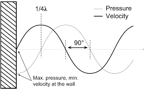
anywhere near the wall, the pressure is maximum, and the speed is zero
However, if you pay attention to observed results, you see absorbers are effective well below a naive application of this rule of thumb. What's going on? A naive application uses wavelength calculated using speed of sound in air. But speed of sound in an absorber is much lower, so the wavelength within the absorber is much shorter. Calculating the wavelength using speed of sound in the absorber gives a much closer match between observed behavior and the 1/4 wavelength rule of thumb for minimum absorber thickness. The surface of a wall-mounted absorber is near a velocity maximum for the lowest frequency for which it is effective.
Interesting related discussion here.
mwmkravchenko
Active Member
One long used trick is to actually hang the absorbent material away from the wall. You again have an greater window of absorption.But they are considering whether it's high pressure or high velocity, perhaps unknowingly, simply by choosing the thickness of the absorber. See below for exposition.
Only if you define "near the wall" as much less than 1/4 wavelength from the wall. So how thick must an absorber be to be effective at a certain frequency? Most quote 1/4 wavelength as a rule of thumb, which puts the surface of the absorber not at all "near the wall" according the that definition. In fact, it puts the surface of the absorber at a velocity maximum, just as the random youtuber claims is most effective.
However, if you pay attention to observed results, you see absorbers are effective well below a naive application of this rule of thumb. What's going on? A naive application uses wavelength calculated using speed of sound in air. But speed of sound in an absorber is much lower, so the wavelength within the absorber is much shorter. Calculating the wavelength using speed of sound in the absorber gives a much closer match between observed behavior and the 1/4 wavelength rule of thumb for minimum absorber thickness. The surface of a wall-mounted absorber is near a velocity maximum for the lowest frequency for which it is effective.
Interesting related discussion here.
Mark
Dmitrij_S
Member
- Joined
- Jun 29, 2020
- Messages
- 8
- Likes
- 9
@NTK Just FYI, I would strongly suggest that anyone working on these notebooks use version 13.2 of Wolfram that recently came out. It looks like they changed something between 13.1 and 13.2 that results in obscene speedups for the FEM solver. I am now able to simulate over 80 frequencies on a high-precision ~19k element mesh in less than 2 minutes. Previously that kind of run would take closer to an hour!
What CPU ? I tried to run NTK's "vsrew_ntk2.ipynb" notebook on my old HP workstation with i7-3740QM CPU (4 physical cores, HT is off), the simulation took approximately 18min. (1100 s.)
What CPU ?
i7-4770.
Similar threads
- Replies
- 4
- Views
- 546
- Replies
- 2
- Views
- 397
- Replies
- 0
- Views
- 263
- Replies
- 15
- Views
- 4K