zeworks
Member
Hi and best wishes for 2023 !
Whilst putting the finishing touches to fixing a Hypex NC122MP amp in an aluminium enclosure, I accidently shorted the Vaux positive auxiliary supply (pin J6.1): there was a hiss in the speakers and the amp went dead - that moment when you want to reverse time by 5 seconds and replay without the silly oversight
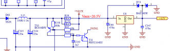
After 30 min off mains, and checking that the SMPS shrinkwraped mains fuse is not blown (tested for continuity), feeding mains again to the board brings the standby SMPS J6.3 pin to nominal 5V, and after asserting the J6.9 PS Enable pin, the Vaux negative auxiliary supply (pin J6.2) is nominal -20V, but the Vaux positive auxiliary supply (pin J6.1) is around 500mV instead of 20V, and the board does not drive speakers when fed audio signal. The J6.7 DC error pin isn't activated.
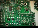
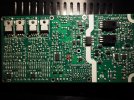
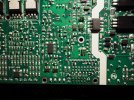
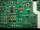
Visual inspection of the top part of the board does not show any signs of arcs or blown components, however removing the bottom heatsink plate shows at least one obvious blown L15 SMD component (pictures attached).
I don't have the design diagrams for the PCB, would anyone be able to put me on the right track to determine what that component value might be ? This L15 is one of those SMD's with no markings that I can see. Maybe there's a way to guess from a measurement of an equivalent component, maybe on the Vaux negative line (say L16 for instance), as there might by some symetry involved asks the newby naively ?
As can probably be guessed I am a just a hobbyist but at ease with DIY, equiped with a Voltcraft VC830 multimeter, a very fine tipped soldering iron, and the will to make good my f***k up however much effort I need to put into it If need be, I can access hot air gun and more advanced measuring instruments.
Many thanks in advance for your help !
Cheers,
Pascal
Whilst putting the finishing touches to fixing a Hypex NC122MP amp in an aluminium enclosure, I accidently shorted the Vaux positive auxiliary supply (pin J6.1): there was a hiss in the speakers and the amp went dead - that moment when you want to reverse time by 5 seconds and replay without the silly oversight
After 30 min off mains, and checking that the SMPS shrinkwraped mains fuse is not blown (tested for continuity), feeding mains again to the board brings the standby SMPS J6.3 pin to nominal 5V, and after asserting the J6.9 PS Enable pin, the Vaux negative auxiliary supply (pin J6.2) is nominal -20V, but the Vaux positive auxiliary supply (pin J6.1) is around 500mV instead of 20V, and the board does not drive speakers when fed audio signal. The J6.7 DC error pin isn't activated.
Visual inspection of the top part of the board does not show any signs of arcs or blown components, however removing the bottom heatsink plate shows at least one obvious blown L15 SMD component (pictures attached).
I don't have the design diagrams for the PCB, would anyone be able to put me on the right track to determine what that component value might be ? This L15 is one of those SMD's with no markings that I can see. Maybe there's a way to guess from a measurement of an equivalent component, maybe on the Vaux negative line (say L16 for instance), as there might by some symetry involved asks the newby naively ?
As can probably be guessed I am a just a hobbyist but at ease with DIY, equiped with a Voltcraft VC830 multimeter, a very fine tipped soldering iron, and the will to make good my f***k up however much effort I need to put into it
If need be, I can access hot air gun and more advanced measuring instruments.Many thanks in advance for your help !
Cheers,
Pascal