Fascinating! I would like to read the science behind this finding. Do you have a link to the data and research that determined these numbers, including examples of devices that follow and/or violate this "rule" and their measurements?hardware devices that work with small signal (phono, preamp, DAC/ADC...) or are very sensitive with the EMI (class D technology) must use aluminum boxes of 4 mm thickness or more

-
WANTED: Happy members who like to discuss audio and other topics related to our interest. Desire to learn and share knowledge of science required. There are many reviews of audio hardware and expert members to help answer your questions. Click here to have your audio equipment measured for free!
- Forums
- Audio, Audio, Audio!
- Amplifiers, Phono preamp, and Analog Audio Review
- Stereo and Multichannel Amplifier Reviews
You are using an out of date browser. It may not display this or other websites correctly.
You should upgrade or use an alternative browser.
You should upgrade or use an alternative browser.
Biblob
Addicted to Fun and Learning
- Joined
- Sep 13, 2018
- Messages
- 635
- Likes
- 603
How come you don't feel the excitement for the possibility that your believes might be irrelevant or non-existant?Now that nobody reads us, I will tell you that I do not follow the SINAD. I prefer to look at other values that I have been referring to for many years.
Taking a look inside you can know a few things, mistakes made and possible improvements. And, above all, very important for me, the love for a job well done or just the desire to earn money.
An example: hardware devices that work with small signal (phono, preamp, DAC/ADC...) or are very sensitive with the EMI (class D technology) must use aluminum boxes of 4 mm thickness or more or the cheapest one, 1 mm galvanized steel sheet (with the precaution of separating almost 10 mm -at least 6 mm- the circuitry from the steel walls).
If you would subject yourself to test yourself, you could save a lot of money, at least.
OP
maty
Major Contributor
- Thread Starter
- #44
Mola Mola, from https://www.mola-mola.nl/contact.php.
The others, by mail: https://nauscopio.wordpress.com/about/

13F8 4F36 3D28 E0F0 348E 54ED B7C4 6A26 A541 1CC8
Last edited:
Maty, you are the person who made the claim of very specific numbers - it is your obligation to back up that claim with references to the data and research - especially when you post specific numbers at a science-based forum.Have you tried to find them?
I have seen the thick aluminum "walls" on Class-D amplifier modules with integrated power supplies like this Hypex UcD example...
...but they appear to be there for heat dissipation. Do they also provide EMF blocking?
(The relationship between magnetism and electromagnetic fields (EMF) can be rather confusing to laypersons - including me. So, any physics experts please - please correct me or expand on my comments if they are inaccurate.)
John Siau's video on the subject of noise in cables demonstrated that EMF interference in audio cables decreases very rapidly with distances - he had to practically make cables touch the source of the interference to easily detect it.)
I also know that some DAC/Amps that measure well have thick cases, and others with similar specs seem to have thinner case walls. I also know that steel is stronger than aluminum, and aluminum sheet is often thicker simply to provide equivalent strength and rigidity.
Perhaps Amir can add some comments related to EMF noise based on his observations while measuring digital components that have external vs internal power supplies, including LPS and SMPS designs.
somebodyelse
Major Contributor
- Joined
- Dec 5, 2018
- Messages
- 3,754
- Likes
- 3,053
I'm another non-expert who'd like to know the source of, and theory behind, the 4mm aluminium claim, as it contradicts my understanding from what I've read on electrostatic, magnetic and RF shielding so far. I've not found any references that thickness beyond a foil is needed for RF or electrostatic shielding. A good conductor with gaps small relative to the wavelentgh to be blocked is apparently a requirement, but not thickness. For magnetic shielding you seem to need a ferromagnetic material (so not aluminium) that's thick enough not to saturate given the field strength you're trying to block. As with all things there may be an issue of what 'good enough' is, or deviations of real materials and structures from 'ideal' at different frequencies, so I'd love to see any references for what makes a particular thickness of steel or aluminium necessary, or what attenuation they provide at what frequency.
If the board is well designed then susceptibility to, and emissions of, electromagnetic interference may be low enough that no screening case is required. The Atom turns in an exemplary performance despite having an unshielded plastic case for example, and a surprising amount of modern test equipment has only a local screening can on particularly sensitive parts of the instrument. Screening cans are usually thin (<1mm, often 0.2-0.3mm) and ferromagnetic according to the datasheets I've seen at suppliers like DigiKey and RS.
EEVBlog #1176 gives a reasonably accessible introduction to EMC and radiated emissions, and how board layout affects it. Others at the same site cover making a DIY probe, and comparing it to commercial ones, although the scopes used are still somewhat expensive. The even cheaper option is to use RTL-SDR instead of the scope. Bruno talks about design for low emissions from class D in his AES presentation 'The Bits In Between' starting on page 124, and susceptibility in the PCB Layout section of 'The G Word' so it's fair to expect they've been been taken into consideration here, at least at the board level. The presentation also shows that this isn't always true! The NC400 docs make suggestions about how to do the input, power and output wiring to reduce interference there, and that's still inside the case. In that sense the photos can show where a manufacturer has done something good or bad with the layout in the case.
Yep. How gullible audiophiles can be. When someone is willing to pay U$15,000 for a USB câble ....I don't know what such claims proves. Does the real world succes of Audioquest, Cardas or Nordost proves something?")
DKT88
Active Member
From what I've read, you're right about thin foil shielding electrostatic fields. The story is different for electrodynamic fields. There the skin depth, frequency, material and thickness are factors. There's a lot of information on the topic but its been too many decades since I took a field theory course to dive into it.I'm another non-expert who'd like to know the source of, and theory behind, the 4mm aluminium claim, as it contradicts my understanding from what I've read on electrostatic, magnetic and RF shielding so far.
I'd love to see any references for what makes a particular thickness of steel or aluminium necessary, or what attenuation they provide at what frequency.
Edit - I tried to post a link to a paper but it didn't work so I attached it.
Attachments
Last edited:
OP
maty
Major Contributor
- Thread Starter
- #50
Off topic
These issues are often ignored by electronic engineers. Waves, transmission / reception, electromagnetic fields, signal processing ...
And it is much worse now, at least in Spain, with the exaggerated specialization. They lack more scientific and engineering culture. But it is a general phenomenon also in Europe Union, since the introduction in the early nineties of the Bologna Plan. Badly implemented in the Study Plans of Spanish Universities.
If the above we join the educational disaster in basic education (PISA)... There have never been so many people with university education in Spain but their educational level is much lower than in previous decades. It is not only a matter of knowledge, but they are incapable of acquiring them on their own. University or not, are unable to think right for themselves, to argue properly.
Unfortunately, it is not an exclusive Spanish phenomenon, at least in "West", aka, EU and NA.
- End off topic -
Last edited:
somebodyelse
Major Contributor
- Joined
- Dec 5, 2018
- Messages
- 3,754
- Likes
- 3,053
Thanks for that, very informative. It appears to include the same graphs @maty posted (thanks for those too.) It still seems to me that the shielding thickness needs to be calculated on a case by case basis though - how much attenuation is needed at what frequencies to achieve target emissions or sensitivities? If there's no measurable performance difference between the board in a plastic case and a metal one in the highest anticipated interference level, and the emissions are below target in both cases, then the metal one is an aesthetic choice not an engineering one. Am I still missing something?From what I've read, you're right about thin foil shielding electrostatic fields. The story is different for electrodynamic fields. There the skin depth, frequency, material and thickness are factors. There's a lot of information on the topic but its been too many decades since I took a field theory course to dive into it.
Edit - I tried to post a link to a paper but it didn't work so I attached it.
Now that nobody reads us, I will tell you that I do not follow the SINAD. I prefer to look at other values that I have been referring to for many years.
Taking a look inside you can know a few things, mistakes made and possible improvements. And, above all, very important for me, the love for a job well done or just the desire to earn money.
An example: hardware devices that work with small signal (phono, preamp, DAC/ADC...) or are very sensitive with the EMI (class D technology) must use aluminum boxes of 4 mm thickness or more or the cheapest one, 1 mm galvanized steel sheet (with the precaution of separating almost 10 mm -at least 6 mm- the circuitry from the steel walls).
Can I refer you to this previous post looking at RFI from a Hypex amp (lack there of).
https://www.audiosciencereview.com/...ements-of-nord-one-nc500-amp.7704/post-181851
With respect you are making the mistake of assumption. As class D has the potential for RFI/EMI etc, that it therefore must have this problem and must be mitigated. This is not the case. Use facts (derived from measurement) to inform. Dont make sweeping statements or generalisations.
OP
maty
Major Contributor
- Thread Starter
- #53
Today we live surrounded by RF/EMI in the houses and more if they are urban concentrations, so the potentiality has become almost certain.
Aluminum is easy to work, to make holes, hence its generalization. But it requires greater thickness.
Years ago I tested with my ODAC, which came in a thin aluminum box. After I while I bought one of those cheap Chinese boxes and the thickness was still insufficient, so I put one box inside the other. It was still insufficient. Taking advantage of a purchase of a 1 mm sheet of galvanized steel to stick it under a wooden shelf (where is the amplifier of my main system, kidnapped by TV and family) I took a few thick steel pieces left over and put them on top and bottom of the first box and the improvement was notorious. Some will say that because of the weight (vibrations) but inside there are no fat condensers, tubes or big transformers.
I also better protected the little internal wiring, a very thin one that passed over the chip and I moved it, noticing improvement (it was the first improvement I made, before buying the new box). It was the first time I used star quad cable in my home improvements. After, I changed too the very cheap headphones cable. Van Damme XKE.
Last edited:
- Joined
- Jun 10, 2018
- Messages
- 6,233
- Likes
- 9,359
Fascinating! I would like to read the science behind this finding. Do you have a link to the data and research that determined these numbers, including examples of devices that follow and/or violate this "rule" and their measurements?
Actually they need solid copper boxes with a direct earth ground. If they can't withstand a nuclear EMP attack, what good are they?
DKT88
Active Member
If there's no measurable performance difference between the board in a plastic case and a metal one in the highest anticipated interference level, and the emissions are below target in both cases, then the metal one is an aesthetic choice not an engineering one. Am I still missing something?
I think you are correct for a normal living environment. Look at amirm's test results of the Atom. I assume was near a lot of other equipment during the test. I just ordered an Atom and have no concerns about it.
I am waiting patiently for one of the experts in RF designs to chime in. .... Hi Don ... I know enough to know the difference between information gleaned from the Internet and real knowledge. ... Hi again Don!
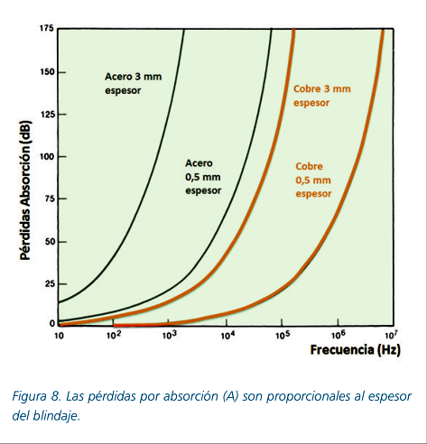
... I know enough to know the difference between information gleaned from the Internet and real knowledge. ... Hi again Don! Considering the curve above, what do you think is the effect of a steel, or aluminium, or copper, shield, obviously properly grounded, on the shielded electronic?
Nothing is simple, especially with EMC.
Let's not complain about the thread folks. I for one like to know what is inside them in absence of access otherwise.
OP
maty
Major Contributor
- Thread Starter
- #60
My last comment about it here. If you want to continue with the discussion, open another thread.
A civil PCB needs a minimum protection of 60 dB. One military between 80 and 100 dB.
The main problem, in audio, usually reaches up to 300 kHz (working bandwidth, not to be confused with the audible, 20 kHz). The most daring audio designers avoid venturing further into interference problems.
The reflection losses are from inside the device, so you do not have to take them into account for the external one, the atmospheric RF -> absortion losses are the important.
Draw an imaginary horizontal line from the middle of the 50 - 75 dB interval and you will obtain the necessary copper thickness.
Similar threads
- Replies
- 12
- Views
- 2K
- Replies
- 4
- Views
- 940
- Replies
- 28
- Views
- 2K
- Replies
- 11
- Views
- 4K