• WANTED: Happy members who like to discuss audio and other topics related to our interest. Desire to learn and share knowledge of science required. There are many reviews of audio hardware and expert members to help answer your questions. Click here to have your audio equipment measured for free!

How to make quasi-anechoic speaker measurements/spinoramas with REW and VituixCAD

MAB

Major Contributor
Joined
Nov 15, 2021
Messages
2,151
Likes
4,838
Location
Portland, OR, USA
I need to thank @napilopez and all of the other contributors on this thread.
index.php


I just need it to stop raining outside so I can move this operation out of my basement shop and get better measurements. My wife would appreciate me moving this outside too, so we agree!!!;)
Less than optimal measurement conditions aside, it hasn't prevented me from making a speaker that sounds OK, and with your help measuring why it is just OK!

Thanks, this thread is gold!
 

dasdoing

Major Contributor
Joined
May 20, 2020
Messages
4,288
Likes
2,759
Location
Salvador-Bahia-Brasil
got me a pair of Realistic Minimus 0.6, a small 2.5" single driver speaker. I wonder how to meassure a speaker diver like that?
 

alex-z

Addicted to Fun and Learning
Joined
Feb 19, 2021
Messages
913
Likes
1,693
Location
Canada
got me a pair of Realistic Minimus 0.6, a small 2.5" single driver speaker. I wonder how to meassure a speaker diver like that?

Same procedure as any other speaker. Line up the measurement mic with the acoustic centre of the speaker, at least 1 metre away, with both the speaker and mic placed as far from any hard surfaces as possible. The closest reflection source limits your gate time, and therefore measurement quality.

Sweep the on-axis response, then repeat for horizontal and vertical off-axis every 10 degrees. For a symmetrical speaker, you can skip half the horizontal measurements, as they will be mirrored.

If the on-axis frequency response of the speaker changes when rotated 90 degrees (horizontal vs vertical) that means your measurement stand is introducing reflections. The speaker should be placed on the edge of the stand, and the entire stand should rotate around the acoustic centre. Meaning that the speaker to microphone distance is constant, and only the angle is changing.
 
OP
N

napilopez

Major Contributor
Forum Donor
Joined
Oct 17, 2018
Messages
2,146
Likes
8,711
Location
NYC
1m away is good for consistency but no, it's not a really that important that the speaker be be 1m away if it's very small. I've measured some small speakers from about 2 feet/0.6m away.
 
OP
N

napilopez

Major Contributor
Forum Donor
Joined
Oct 17, 2018
Messages
2,146
Likes
8,711
Location
NYC
I actually began the process of a complete rewrite a couple of weeks ago and eventually plan to 'open source' the guide so it can be updated by the community to include relevant updates in REW and VituixCAD. The software evolves faster than I am able to keep up with now that I am no longer measuring speakers several times a month as I used to =]

Updates include:
  • Updating the guide so it can be done all in REW and VituixCAD. I'll leave the Bagby sheet only as a reference/alternative in an appendix or something.
  • Formalizing the language while maintaining accessibility.
  • I'll also be updating the language to be a bit more broad -- as it currently assumes the reader has been following conversations about speaker measurements on ASR and the like.
  • Rewriting the off-axis nearfield bass merger process to include optional(recommended?) use of VituixCAD's 'force to gradient' feature.
  • Updating to include a recent REW feature that allows you to take multiple measurements on a time delay rather than repeating the measurement multiple times
  • Recommending using default REW Tukey 0.25 setting by default (I personally still prefer the rectangular window for reasons explained earlier in the thread, but it's not that big of a deal and not that important as an extra step).
  • Emphasizing final visual presentation in VituixCAD -- reimporting back to REW will be an optional appendix.
However, one thing I will not be doing is making the guide needlessly brief. I would rather repeat myself, include additional steps for clarity, and keep the word count high than try to make the guide too concise. I often think simplicity comes at the expense of accessibility.

That said, I'll also work to create a TL;DR version for those who may be more knowledgeable or only need a refresher.

There are a few things I'm still trying to decide on. For example, I do still prefer to use REW for summing the bass responses, especially when there are more than two drivers or with active speakers. I like the alignment tool for visualizing timing issues, and as more people are familiar with REW than VituixCAD on this forum, I think it might make sense to keep some more steps in REW. Although more people are creating full spinoramas using this guide than I expected, most are still just doing on-axis measurements. So other than for baffle step, you can do most of that in REW. Not sure yet though how the exact balance will end up.

But yes, a rewrite is coming.

Please keep in mind I wrote this guide over a few days after multiple people had reached out to me about my process. At the time there was no end-to-end guide for taking quasi-anechoic measurements with REW, summing the nearfield response, and ending up with a spinorama. I never claimed my process was the most efficient, nor did I expect it to be stickied; it was just my own workflow at the time. Thank you for your patience.
 
Last edited:

dcibel

Member
Joined
Feb 8, 2021
Messages
42
Likes
49
I'm not active on this forum, but as an avid DIY speaker design/builder and experienced VituixCAD'er I thought I'd chime in here on this instruction and potential updates.
  • Recommending using default REW Tukey 0.25 setting by default (I personally still prefer the rectangular window for reasons explained earlier in the thread, but it's not that big of a deal and not that important as an extra step).
I'd actually recommend tukey 0.75 or cosine function, included in latest 5.20.14 early access release, as it provides minimal over/undershoot on low end of windowed response for best overlap with nearfield measurement.
There are a few things I'm still trying to decide on. For example, I do still prefer to use REW for summing the bass responses, especially when there are more than two drivers or with active speakers. I like the alignment tool for visualizing timing issues, and as more people are familiar with REW than VituixCAD on this forum, I think it might make sense to keep some more steps in REW. Although more people are creating full spinoramas using this guide than I expected, most are still just doing on-axis measurements. So other than for baffle step, you can do most of that in REW. Not sure yet though how the exact balance will end up.
Alignment tool is just gain + delay, all of which is already available in VituixCAD merger tool. It seems needlessly complicated to be processing diffraction in other software, bring into REW, then use alignment tool, arithmetic functions, export back to VituixCAD for use in merger. Just measure far field and near field from speaker, window and export, then in VituixCAD use diffraction and merger tool. Combining near field, port output, diffraction, gain and delay adjustment, all done in merger tool. Avoiding all these extra steps in REW is what can make the instruction simplified.
At the time there was no end-to-end guide for taking quasi-anechoic measurements with REW, summing the nearfield response, and ending up with a spinorama.
Keep in mind that VituixCAD measurement guide for REW has existed in the VituixCAD help page since 2019, only difference with this guide is the lack of loopback timing reference since combining multiple measurements sets is not being done, only evaluation of complete speaker as a whole. Only minor modifications for steps provided in VituixCAD help file will get you the required results. FWIW The REW guide for VituixCAD could use an update as well to include recent updates to features of merger tool and REW.
 
OP
N

napilopez

Major Contributor
Forum Donor
Joined
Oct 17, 2018
Messages
2,146
Likes
8,711
Location
NYC
Thank you for your input!

I'd actually recommend tukey 0.75 or cosine function, included in latest 5.20.14 early access release, as it provides minimal over/undershoot on low end of windowed response for best overlap with nearfield measurement.

Using a smoother function (and my reluctance) was discussed earlier in the thread.

My experience isn't much with DIY but with measuring commercial speakers. That's allowed me to compare my results to anechoic results from the NFS or an anechoic chamber on at least 15 occasions and I have quite consistently found that using a more rectangular window tends better track the anechoic measurements. In particular, using a smoother window function will tend to obscure narrow resonances in the lower midrange that are otherwise visible.

So I think 0.25 is a good compromise, personally. I haven't found an issue with overlapping the nearfield measurement this way and anecdotally I think it tends to track the nearfield measurement better too. I'd be happy to include a blurb on what the effect of different windows but I'm still learning towards a sharper one.

Alignment tool is just gain + delay, all of which is already available in VituixCAD merger tool. It seems needlessly complicated to be processing diffraction in other software, bring into REW, then use alignment tool, arithmetic functions, export back to VituixCAD for use in merger. Just measure far field and near field from speaker, window and export, then in VituixCAD use diffraction and merger tool. Combining near field, port output, diffraction, gain and delay adjustment, all done in merger tool. Avoiding all these extra steps in REW is what can make the instruction simplified.

Makes sense.
 

kimmosto

Active Member
Joined
Sep 12, 2019
Messages
215
Likes
513
It's fact that too short or shallow window function damages magnitude response by smoothing narrow band deviations (NBD) at the midrange, but too steep window functions could cause deviations and hump.
1672380703888.png

Errors can be minimized by merging near field LF and far field HF above frequency range including "too much" error. Challenge is that large radiating area requires adequate measurement distance to be proper far field without near field effects. Longer measurement distance requires longer distance to reflecting boundaries.
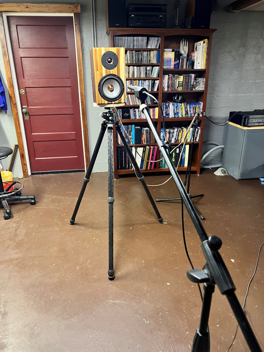
Measuring outdoors speaker above 2 meters could allow measuring also large constructions at >1 meter with close to 10 ms time window which passes also NBD at mid-range. But really large and complete (with XO) tower constructions with large woofers or long distance between different drivers require "full" measurement distance of 2 meters. People living in continuous winter or rainy or windy climate are forced to measure indoors. Height of the room is not necessarily more than 2.5 meters so measurement distance must be quite short (<4.5 ms) and time window cannot be very steep especially with larger woofers to avoid merging at the error hump causing wrong LF/HF balance to the result response. In critical cases shallower window function such as Tukey 0.50, Tukey 0.75 or Cosine could be better compromise though NBD could be quite much smoothed. So @napilopez you cannot recommend single steep window function type without specifying also few other parameters such as maximum radiator size and reflection-free time in IR. You can recommend outdoor measurements for sure, but there may be close to no one who can really use it.

I have tested some mathematical tricks to extend time-windowed measurements to lower frequencies. For example "Extending Quasi-Anechoic Electroacoustic Measurements to Low Frequencies" by Eric Benjamin introduces few possible methods. Some other papers in AES e-Lib related to cepstrum:
1672382880911.png

Maybe JohnPM could try to add some good method to REW, without too many subjective parameters to get decent result.

As already mentioned, measuring complete speaker including XO is big part of the problem due to distance differences between the radiators. Quasi-anechoic measurement is usually suitable for small speakers only. Measuring individual drivers enables shorter measurement distance and longer or steeper time windows (compared to full construction), but unfortunately disconnecting individual drivers is not always accepted, or multiple woofers could have shared box volume reducing accuracy of measurements. Combining responses of multi-way requires also time-locked measurements so Umik-1 etc. is not the best option.

Designing good speakers is much more important goal (imo) than reviewing and judging them after a mistake has already happened. Measurement instructions for VituixCAD introduces method to measure individual drivers because the tool is meant for designers - to make commercial reviewing of very basic frequency response features as unnecessary as possible.
 
Last edited:

kimmosto

Active Member
Joined
Sep 12, 2019
Messages
215
Likes
513
One small thing about NBD. Certain deviation spectrum could be "just" feature of individual driver. It is unfortunate but natural that all drivers in the same manufacturing batch are not identical - no matter price tag. Usually at least two but sometimes four driver individuals could be required to design good average crossover for whole series. QC measurements, pair matching and designing individual crossover is possible especially as active, but it's probably very rare. Accurate measurement of NBD at mid-range is not a bad idea because vent and box could also cause NBD, but the result should be representative in a larger sample if a driver is the source.
 

dcibel

Member
Joined
Feb 8, 2021
Messages
42
Likes
49
Errors can be minimized by merging near field LF and far field HF above frequency range including "too much" error. Challenge is that large radiating area requires adequate measurement distance to be proper far field without near field effects. Longer measurement distance requires longer distance to reflecting boundaries.
This is a good point to make, and I believe good reason that CTA-2034-A calls for 2m distance. 1m may be adequate for small bookshelves, but especially for large towers or line arrays which may have drivers near floor level, the response from 1m to 2m is not just a problem of diffraction, but simply the distance from speaker driver to mic which will affect the recorded tonality of the speaker. Essentially, large speakers will not sound the same at 1m as they do at normal listening distance of 2-3m.

Here's an example, a large 3-way speaker with woofer located at floor level. Difference between response at 1m (soilid white) vs 2m (blue dashed) is quite significant. These problems make effective evaluation of large speakers indoors a bit difficult.
project3 var3 SPL compare.png


I have tested some mathematical tricks to extend time-windowed measurements to lower frequencies. For example "Extending Quasi-Anechoic Electroacoustic Measurements to Low Frequencies" by Eric Benjamin introduces few possible methods. Some other papers in AES e-Lib related to cepstrum:
View attachment 253382
Maybe JohnPM could try to add some good method to REW, without too many subjective parameters to get decent result.
It's rare that I see references to "cepstral techniques". I recall when I used SoundEasy, it included a cepstrum editor which was quite convoluted to use, but essentially allowed one to edit out reflections from an impulse response. In SE its a completely manual process, so completing that for a full set of spatial data would be very tedious, but I'm sure some clever response slope matching it could be somewhat automated in software. It's an interesting idea to be able to use a longer window and possibly avoid nearfield entirely for this sort of evaluation.
 

MAB

Major Contributor
Joined
Nov 15, 2021
Messages
2,151
Likes
4,838
Location
Portland, OR, USA

kimmosto

Active Member
Joined
Sep 12, 2019
Messages
215
Likes
513
This is a good point to make, and I believe good reason that CTA-2034-A calls for 2m distance. 1m may be adequate for small bookshelves, but especially for large towers or line arrays which may have drivers near floor level, the response from 1m to 2m is not just a problem of diffraction, but simply the distance from speaker driver to mic which will affect the recorded tonality of the speaker.
Measuring one driver at a time makes designing for example this kind of speaker very easy and fast. It's just like any smallish speaker with 8" woofer to measure and simulate for XO design. But reviewers will have terrible headache or back pain or both when trying to measure whole construction in two planes at 2m.
DYN_Evidence_Master_rosewood.jpg
 
OP
N

napilopez

Major Contributor
Forum Donor
Joined
Oct 17, 2018
Messages
2,146
Likes
8,711
Location
NYC
Thank you for both for your further insights.

So @napilopez you cannot recommend single steep window function type without specifying also few other parameters such as maximum radiator size and reflection-free time in IR. You can recommend outdoor measurements for sure, but there may be close to no one who can really use it.

Fair enough. This was written primarily for those measuring bookshelf/small speakers in mind, but it's not as clear as it should be in the text. There are certainly more challenges to measuring towers though ultimately it mostly come down to how far you can get the mic from the speakers while keeping a wide enough gate.

I usually use 6.5ms as a window and I suggest in the guide to try achieve at least a 5ms window. I believe within these parameters a steeper window is usually more beneficial than not. But information about minimum time windows can be made clearer as well, including some guidelines on the minimum amount distance to walls including ceiling height that would allow a speaker to be reliably measured indoors.

I still think it's worth recommending outdoor measurement where possible. It seems maybe a third of people who have used this guide are measuring their speakers outdoors, perhaps more. While you are beholden to the weather and the setup can be annoying for large speakers capturing the measurements doesn't take too long and REW is generally quite resilient to noise. Obviously the quieter and more controlled your environment the better. I miss my old apartment with 4.5m/15-foot ceilings...


Designing good speakers is much more important goal (imo) than reviewing and judging them after a mistake has already happened. Measurement instructions for VituixCAD introduces method to measure individual drivers because the tool is meant for designers - to make commercial reviewing of very basic frequency response features as unnecessary as possible.

I certainly appreciate what you've done with VituixCAD as well as the way you've quickly implemented feedback. I definitely agree that designing more good speakers in the first place is a more important goal! That said, when I wrote this it was my job to review speakers though and I'm afraid more people will be buying speakers than making them for quite some time!
 

JohnPM

Senior Member
Technical Expert
Joined
Apr 9, 2018
Messages
344
Likes
919
Location
UK
I have tested some mathematical tricks to extend time-windowed measurements to lower frequencies. For example "Extending Quasi-Anechoic Electroacoustic Measurements to Low Frequencies" by Eric Benjamin introduces few possible methods.
Richard Stroud presented a paper in 2010 building on that impulse shortening approach, "Quasi-Anechoic Loudspeaker Measurement Using Notch Equalization for Impulse Shortening". We had some discussions about the method ahead of publication. My main concern about those approaches is they are not really measurements, they are a process for building a good (or good enough) model of the speaker or driver's low frequency behaviour that in essence ends up being substituted for the measurement result below the IR window cut-off. It isn't obvious to me what benefit that brings beyond what can be achieved using a near field measurement, which is necessary to build the model in the first place, but I'm no speaker designer and I expect there is more to it that I'm not recognising. Beamforming looks more promising, as has been discussed elsewhere here as I recall.
 
OP
N

napilopez

Major Contributor
Forum Donor
Joined
Oct 17, 2018
Messages
2,146
Likes
8,711
Location
NYC
Colocación del micrófono: si el micrófono se coloca en el punto medio entre los centros acústicos y se deja allí para ambas mediciones.

Buena tarde.

Te escribo desde España con traductor.

Estoy interesado en la técnica de "colocar el micrófono en el punto medio entre los centros acústicos" y necesitaría más información que no encuentro. Agradecería más información.

Feliz 2023

Si quieres, enviame un mensaje directo para explicarterlo mas claro en español.
 

kimmosto

Active Member
Joined
Sep 12, 2019
Messages
215
Likes
513
Quick study with few time windows and two lengths. Results of this kind of tests are case-dependent, but this shows that steeper window function does not reveal much more actual details if window is shortish - typical for indoor measurements. Too steep windows just ruin overall response and add deviations which look details. Extending time window from 4.5 to 7 ms drops lowest usable merging frequency, but does not give much more actual details to low mid. Cosine 0.75 looks the best in this group.

Window_function_cmp_4.5ms.png


Window_function_cmp_7.0ms.png
 

kimmosto

Active Member
Joined
Sep 12, 2019
Messages
215
Likes
513
...they are not really measurements, they are a process for building a good (or good enough) model of the speaker or driver's low frequency behaviour that in essence ends up being substituted for the measurement result below the IR window cut-off.
Matching filter before and after window function does not have to be very accurate match with actual system (/Eric Benjamin). Result of my test was not good and easy enough, subjective adjustment was required and method is also sensitive to noise at LF. Traditional NF+FF merging is okay so I probably continue without fancy math tricks.
 

kimmosto

Active Member
Joined
Sep 12, 2019
Messages
215
Likes
513
2023-01-21: Quick manual to produce measurement data with REW updated for revision V5.20.14ea27 (or later): VituixCAD_Measurement_REW.pdf
Refresh to see the latest pdf version.
Note! REW V5.20.14ea27 is still early access version, and some features could change. But it's the first revision where full dual channel measurement works i.e. features for speaker measurements match with ARTA and CLIO.
 
Top Bottom