What does that mean? Audible?The hump is way over the noise level, picture posted here somewhere.

-
WANTED: Happy members who like to discuss audio and other topics related to our interest. Desire to learn and share knowledge of science required. There are many reviews of audio hardware and expert members to help answer your questions. Click here to have your audio equipment measured for free!
You are using an out of date browser. It may not display this or other websites correctly.
You should upgrade or use an alternative browser.
You should upgrade or use an alternative browser.
How to Fix ESS Hump on SGD1 and LA-QXD1
- Thread starter Ben1987
- Start date
Count Arthur
Major Contributor
- Joined
- Jan 10, 2020
- Messages
- 2,239
- Likes
- 5,022
What does that mean? Audible?
Yes, every female vocalist sounds like Edith Piaf.
")
Hilarious !!!Yes, every female vocalist sounds like Edith Piaf
But, no kidding aside, I've thoroughly enjoyed this thread! I'm just a homespun hobbyist and armchair amateur, but the wealth of information, ideas, and potential solutions coming from true experts and professionals (who remain real-world audio enthusiasts) that contribute to this forum amazes me, and never so much as in this thread. Didn't even notice it [this thread] until today because I was so focused on getting the Topping D90 MQA (MQA? - yeah, I know
).Anyways, congrats and huge thanks to you, Amir, for developing and maintaining this forum; and also to all of you who take part in this forum and elevate the collective discussion and knowledge herein. Particular kudos to Ben of Soncoz for really trying to make (and then remake) a better product. Wish that all manufacturers could have someone like him to influence their product development, improvement, and release. This is so refreshing compared to forums where participants talk of "veils upon veils" being lifted after adding even yet more dubious products to their systems !!!
PS. Also, thanks, Amir, because now I feel obligated to contribute to that den of lazy panthers you keep around
Last edited:
https://www.audiosciencereview.com/...ss-hump-on-sgd1-and-la-qxd1.10502/post-299041Question, if I purchase product thru Amazon in US, will I get product with issue fixed or I need to send it back to maufacturer to get the fix ?
AllanDavidson
Member
- Joined
- Feb 10, 2020
- Messages
- 90
- Likes
- 34
M4 has 9016 which is the much earlier generation. The noise modulation of 901x is very different from the IMD hump later on.@amirm review's of the Motu M4 also shed light on the unit's dreaded IMD hump.
Would this procedure also works on the Motu?
In short, no. Same procedure won't help.
AllanDavidson
Member
- Joined
- Feb 10, 2020
- Messages
- 90
- Likes
- 34
M4 has 9016 which is the much earlier generation. The noise modulation of 901x is very different from the IMD hump later on.
In short, no. Same procedure won't help.
Well, that's unfortunate.
Thank you.
Finally on this sunny Sunday, I scheduled a time to share the ESS hump repair solution.
The following method only verifies the two SONCOZ DACs SGD1 and LA-QXD1, both of them using ES9038Q2M DAC chips, and the others are only referrals.
To save you time, first put forward the method and conclusion: For the ES9038Q2M DAC chip, adjusting the combination of resistance and capacitance values of its IV converter and LPF circuit can fix the hump problem,and it belongs to the hardware repair scheme.
The following is the process of my verification:
2019-12-10-13:30
To start my validation and repair, first do nothing, look at the hump, it looks like this:
View attachment 43299
This hump is so ugly that I have overlooked this problem. Please forgive the unprofessional design process.The blue channel is the channel I started to adjust, and the red channel is the contrast channel, which is easy to distinguish.
I used two different OPAs in my design. First, I started changing the (IV and LPF) OPA’s placement. But unfortunately, the hump still stands out:
View attachment 43300
This is then verified using higher precision resistors. The resistance with 1% precision is used in the design. I have prepared for it and purchased a variety of resistance with 1‰ precision in advance.
View attachment 43301
The change of hump is not obvious, so it seems that the resistance precision is not to blame. Other work needs urgent attention at this time, so the verification work will be delayed a little.
2019-12-12 16:20
When I finally had time to continue my verification, I did some calculations, mainly the bandwidth calculations for the IV circuit. Normally, the larger the bandwidth design of the IV circuit, the more noise it may bring as a result, so the design should only meet the bandwidth of the audio signal. The design bandwidth of the IV circuit is around 130kHz, and I get good other parameters in this bandwidth, such as THD+N, linearity, SNR, crosstalk and so on.
I doubt that changing the bandwidth will bring the performance parameters I've already tuned to degrade the overall performance of the product.
View attachment 43303
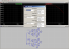
The following is a manuscript of my calculations, in which I calculate various combinations of IV resistance and capacitance values in a bandwidth range of 130khzkz-500khz.
View attachment 43304
But the end result was a slap in the face, and the hump remained the same.
I decided to leave the IV circuit for a while and try to adjust the capacitance of the LPF circuit. The original design was 1nF and adjusted to 2.2nF, 3.3nF, and 4.7nF. It turned out that 2.2nF worked best, as follows:
View attachment 43305
The blue channel does go down, but that seems to be the limit of how far it can go down, and that's a big enough distance to be stationary.
Well, I think I'm hungry. I need to have dinner and clear my head.
2019-12-12 20:00
After dinner, I will continue to verify the bandwidth of the IV circuit. Who set the maximum bandwidth of 500kHz for me? Why don't I try it higher? I think there's a ghost here. I have to try it right now. I adjusted the capacitance of the IV circuit from 470pF to 100pF. Here's the result:
View attachment 43306
I couldn't believe my eyes and the hump had shrunk. I feel like I'm close to finding out the truth.
I then adjusted the capacitance on such a basis and found that the effect of the 150pF capacitor was optimized well:
View attachment 43307
However, the value of this capacitor is not some conventional value, and it may be difficult to purchase in mass production. Now that I have found the direction, and look at my messy laboratory, I think I need to sleep:
View attachment 43308
Well, get some sleep and continue the test tomorrow, 2019-12-12-22:30
2019-12-13 10:40
I kept the machine running last night to see how its thermal stability was:
View attachment 43309
The thermal stability is good, it doesn't affect the hump, which is good news.
According to the thinking and direction of yesterday, there is still a resistance of 100R in the IV circuit. There should also be room for adjustment of this parameter. Let's try to adjust to 75R first, as shown in the figure below:
View attachment 43310
It's getting smoother, it's showing up, keep checking, adjust 39R, look at the picture:
View attachment 43311
It's a little smoother and smoother. Happy. Keep going. 51R. Look at the picture:
View attachment 43312
And finally, after a couple of tests. The capacitance value is set at 220pF and the resistance value is set at 51R. I feel that this is the result I want, so I modify the device of the two channels and adjust the output amplitude. The result is as follows:
View attachment 43313
So far, I think the hump problem has been solved, ignoring the channel difference caused by my manual welding. However, this hump is really so sensitive that it is hard to catch like a ghost. The adjustment of resistance and capacitance parameters is very small and hump changes a lot.
To verify my solution, I continued to experiment with the method on LA-QXD1. Again, the blue channel is the adjusted channel:
View attachment 43317
It looks amazing, it's smooth all at once, so I'm going to change the other channel, the red channel, and I'm going to look at the picture:
View attachment 43315
OK, I think the solution is feasible and verified here. I am very glad to share these experiences. It is a very interesting experience, and it also encourages me to truly achieve the product technology.
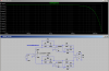
Finally, the circuit before and after the hump is pasted for comparison:
View attachment 43316
SGD1 and LA-QXD1 correct the hump in the same way, so the comparison diagram of SGD1 can be posted here. Of course, someone mentioned the possibility of a software fix before. I only tried to turn off and turn on the register related to
Fantastic work Ben! Looking at the shematics mods you have pulished, if my understanding is correct, the analog stage output is dc coupled and I am very happy obout it. Can you please confirm dc output for the SGD1 please? My friend MBL'er came to my home and tried your DAC and I must say that it is great even compared to my Bladelius Embla!
As my Embla cannot read DSD I will buy your DAC!
As my Embla cannot read DSD I will buy your DAC!
OP
- Thread Starter
- #93
XlR@4V 200ΩCan you please confirm dc output for the SGD1 please
RCA@2V 100Ω
markk02474
Member
Great work Ben! I just read this fantastic thread after getting an email from the site, so catching up.
So, the cause of the IMD humps with ESS DACs is a DAC setting in software? Filter calculations not matching reality? DAC chip output specs not matching reality so filter calculations off? Fantastic to see how experimentation and empirical observations produced such fine results!
So, the cause of the IMD humps with ESS DACs is a DAC setting in software? Filter calculations not matching reality? DAC chip output specs not matching reality so filter calculations off? Fantastic to see how experimentation and empirical observations produced such fine results!
Looks like any DAC with current source outputs has best linearity if load behaves like zero impedance load. Signal applied to the inverting input of opamp with shunt feedback subject to such loading condition. Please take a look at pictures attached.
In case of wideband RF signals it is hard to provide wideband "Zero impedance" conditions and only non reflective 50Ohm load allows lowest possible intermodulation distortions.
In case of wideband RF signals it is hard to provide wideband "Zero impedance" conditions and only non reflective 50Ohm load allows lowest possible intermodulation distortions.
Attachments
Hi, @Ben1987. Congrats on solving the ESS "hump". I am a DIYer and wondering if you have any plans on selling bare board versions of your DACs to the DIY community? I like to build my own power supplies, enclosures, etc. I am building a streaming player now with a Pi and a Tone 1 inside but would be interested in one of your boards as well.
BTW @Ben1987, I just noticed this LA-QXD1 listing on Amazon: https://www.amazon.com/SONCOZ-Silver-Digital-Converters-Balanced/dp/B089KKKVM3?th=1 by seller "youyeetoo tech" with the following description, which I think is totally wrong:

- ♪ Two of the best performing mic preamps the Soncoz range has ever seen, now with Filter modes switching to give your recordings a brighter and more open sound.
- ♪ POWERFUL DECORDING PERFORMANCE - High-performance converters enable you to record and mix at up to 24-bit/ 192kHz.
markk02474
Member
http://twistedpearaudio.com/landing.aspx has been doing ESS DIY DAC etc. components for years.Hi, @Ben1987. Congrats on solving the ESS "hump". I am a DIYer and wondering if you have any plans on selling bare board versions of your DACs to the DIY community? I like to build my own power supplies, enclosures, etc. I am building a streaming player now with a Pi and a Tone 1 inside but would be interested in one of your boards as well.
Yeah - but a Buffalo-IIIse (ES9028/38) board in a usable configuration is over $400 US and that does not include the output stage. They don't seem to offer an ES9038Q2M-based board.http://twistedpearaudio.com/landing.aspx has been doing ESS DIY DAC etc. components for years.
iancanada over at DIY Audio offers a dual-mono ES9038Q2M assembled Pi hat DAC board for $85 and a couple of output stage boards with choices of I/V Op amp or transformer-based. I have considered going that route in the past, but have not seen in-depth measurement workups. I have ordered one of his ESS controller boards to connect with my Tone 1.
His stuff is on Github: https://github.com/iancanada/DocumentDownload
Last edited:
Similar threads
- Replies
- 58
- Views
- 8K
- Replies
- 136
- Views
- 27K
- Replies
- 11
- Views
- 1K
- Replies
- 12
- Views
- 2K