• WANTED: Happy members who like to discuss audio and other topics related to our interest. Desire to learn and share knowledge of science required. There are many reviews of audio hardware and expert members to help answer your questions. Click here to have your audio equipment measured for free!

Headphone Amplifier Circuit Design

C

crystallin

Guest
I've always wanted to build my own headphones and was curious if anyone here has any experience or tips as I am not sure if the circuit can work.
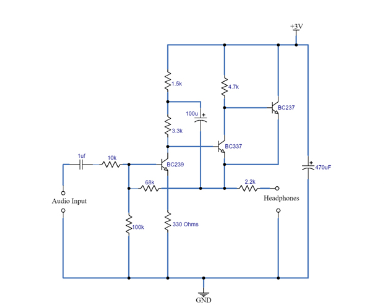
The components I will use are as follows:
Breadboard
Battery
ceramic capacitor
Resistors
polar capacitor
BC237 NPN transistor (datasheet)
BC239 NPN transistor(BC239 DATASHEET)
MIC
Audio Jack

Here is the circuit.
1676873367846-png.60452
 

Doodski

Grand Contributor
Forum Donor
Joined
Dec 9, 2019
Messages
21,543
Likes
21,829
Location
Canada

jasonRF

Member
Joined
May 21, 2021
Messages
6
Likes
21
Location
New England
Building a headphone amplifier with discrete components can be fun, but that circuit will not be useful. Without even trying to understand exactly how it is supposed to work, it is clear that it will have significant DC on the output which could in principle damage headphones. Also, it is a pure class A design with bias currents under 1 mA (3V supply with resistors of a few k) so will not be able to deliver any current without massive distortion. Where did you find this circuit, and what kinds of headphones was it designed for?

edit: if you do not have much experience with electronics, I would suggest an opamp-based amplifier to start, such as a Cmoy headphone amp you should be able to find a lot of info about online. The chip mentioned by Doodski can produce exceptional performance, but you should probably only attempt to use it if you have some experience with electronics. Usually a part with 110 MHz bandwidth takes some know-how to keep stable, and probably will not work on a breadboard at all.

jason
 
Last edited:
Top Bottom