• Welcome to ASR. There are many reviews of audio hardware and expert members to help answer your questions. Click here to have your audio equipment measured for free!

HALS - Holographic Acoustic Loudspeaker Scanner

d.fapinov

Member
Joined
May 29, 2026
Messages
40
Likes
198

HALS - Holographic Acoustic Loudspeaker Scanner​

After more than a year of development, testing and discussion, we believe HALS has reached the point where it can be presented as a usable project rather than only as a development journey.

HALS is, in essence, a DIY alternative to a Klippel-style Near Field Scanner: an automated system that measures a loudspeaker at many positions in the near field, then uses spherical harmonics to reconstruct a continuous three-dimensional model of its sound field.

This “holographic” model has two major advantages over a conventional horizontal or vertical microphone sweep:
  • It can separate the loudspeaker from the room’s influence, providing effectively anechoic measurements.
  • The reconstructed sound field can be evaluated at many locations in three dimensional space - from only 5 cm from a port, where cabinet leakage and local behaviour can be examined, to a position 50 metres away for evaluating true far-field performance.
HALS is an independent community driven project and is not affiliated with Klippel.

The project grew primarily out of collaboration between Dimitri, Tom and Jan, as well as lengthy and productive discussions with many users here and on DIY-Audio.com. The original development threads contain a great deal of background, experimentation and problem-solving, but they have inevitably become rather long.

This thread is intended to provide a cleaner introduction to the HALS system as it exists today and a central place for new users.

splash.png


What does HALS do?​

HALS moves a measurement microphone through a cylindrical cloud of points around a stationary loudspeaker. At every position, it plays a sine sweep and records the loudspeaker’s impulse response. Typical measurement grids contain between 500 and 2,000 points.

The resulting collection of measurements is processed in HALS Studio, where the measured sound field can be reconstructed and analysed. HALS Studio can also generate FRD files and impulse responses for use in other software.

In practical terms, the complete workflow is:

  1. Mount and align the loudspeaker, then home the scanner.
  2. Tell the software the approximate size and position of the loudspeaker by jogging the microphone to key reference points, such as the baffle edge and tweeter.
  3. Let the software automatically generate a measurement-point cloud containing the chosen number of points.
  4. Let the scanner record an impulse response at every position. Depending on the grid and measurement settings, this typically takes between one and four hours, but the process is automated.
  5. Process the resulting measurement set in HALS Studio.
  6. Explore the response and directivity by interacting with the reconstructed sound field in 3D, placing virtual microphones and using the available analysis tools.
  7. Export plots, frequency responses, impulse responses and other results for further use.
HALS is not intended to be a direct copy of a commercial scanner, and it comes with no guarantees of accuracy or support. It is a practical DIY implementation based on accessible components including extensive use of 3D printing, open-source software and documented methods.

The documentation is still a significant area of ongoing work and will continue to improve.

HALS-ROBOT-Sept-2026.png


The three parts of HALS​

1. Measurement and scanner-control software​

The acquisition software controls the robot, generates the measurement grid, handles audio playback and recording, and manages the complete automated scanning sequence. It produces measurement-session folders that can be opened directly in HALS Studio.

The desktop application includes:

  • Audio-interface and channel configuration
  • A cylindrical measurement-grid generator
  • Scanner calibration, homing and manual jogging
  • Automated measurement runs
  • Multiple-sweep averaging
  • Dual-channel capture for timing alignment
  • Farina-style exponential-sine-sweep deconvolution, separating the linear and nonlinear components of the impulse response
  • Live impulse-response and frequency-response displays
  • A mock mode for exploring the workflow without connected hardware
Windows installer:
Release v0.3.0 — TomKamphuys/NFS

Source code and documentation:
https://github.com/TomKamphuys/NFS

1788381064142.png

1788381189479.png


2. HALS Studio​

HALS Studio is the companion desktop application for processing and analysing the measurements made by the scanner.

Its workflow is organised into three main workspace areas:

  • Process — prepares the measurement set and performs the sound-field processing.
  • Analysis — provides advanced tools for evaluating the response, directivity and time-domain behaviour of the reconstructed sound field.
  • Export — generates FRD files and impulse responses at specified virtual-microphone positions for use in other applications, such as VituixCAD and REW.
Windows installer:
HALS Studio initial release

Source code and documentation:
https://github.com/dfapinov/HALS-Studio

Short HALS Studio tutorial:

Process:
process_screenshot.png


Analyze:
analysis_screenshot.png


Analyze:
analysis2_screenshot.png


Export:
export_screenshot.png


3. Scanner mechatronics​

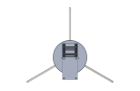
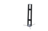
The physical scanner uses a rotating arm carrying a microphone assembly that can move both radially and vertically. In other words, it uses a cylindrical kinematic system. The device under test stands on a central platform and does not rotate.

The published design uses:

  • A steel tripod and central pillar
  • Standard aluminium profiles and assembly parts
  • Stepper motors and geared stepper motors
  • A BTT 3D-printer motion-control board running GRBLHAL firmware
  • Timing-belt-driven rotary and linear axes
  • Commonly available bearings, shafts and other mechanical parts
  • Approximately 80 3D-printed components
The present machine has an enclosing diameter of approximately 2.7 metres and a height of approximately 2.3 metres. Other builders could reasonably use different radial- and vertical-axis lengths to suit their available space and measurement requirements.

The mechatronics repository contains the Fusion 360 model, STEP files, bills of materials, design decisions, photographs and construction information for the main assemblies.

Hardware repository:
https://github.com/JanRSmit/HALS-Mechatronics

Jan's Scanner Build:
HALS-Robot--01.jpg


Getting started​

If you are mainly interested in understanding the workflow, both HALS Studio and the scanner-control software can be explored before building the complete robot. The acquisition software includes a mock mode, allowing a measurement run to be rehearsed without connected hardware.

A practice dataset for analysis and export is also available:
PRACTICE DATASET - Elac Debut 2.0

Its results can be compared with independent measurements published by >ASR< and >Erin’s Audio Corner<.

However, a more robust validation is to compare the HALS prediction against a direct measurement of the DUT at a position that was not part of the input dataset.

Acid_Test.png

The measurement point shown above was not included in the HALS input data. The HALS model was used to predict the complete response at this position, which was then compared with a direct in-room measurement at the same coordinates. Some differences in smoothing remain visible as HALS uses Frequency dependant Windowing.

The download does not contain the complete input dataset of almost 2,000 impulse-response WAV files, as these require several gigabytes of storage and are impractical to host indefinitely. Instead, it contains the preprocessed holographic model—the _coefficients.h5 and _project.json files—which can be opened in HALS Studio.

For an actual scan, the main requirements are:

  • A completed scanner
  • A measurement microphone
  • An audio interface with ASIO support and at least two input and two output channels (Focusrite Scarlett 2i2, MOTU M2, Behringer UMC202 etc..)
  • A power amplifier and loudspeaker under test, or an active loudspeaker
  • A Windows 10 or Windows 11 computer connected to the audio interface and motion controller
The HALS Control software can run on a relatively low-powered computer, as it only needs to control the scanner position and play and record audio.

Processing in HALS Studio requires a reasonably modern system because the computational load can be significant and the application uses hardware-accelerated graphics. Modern integrated graphics should be sufficient.

Project status​

HALS should still be regarded as a developing DIY project, but the complete chain is now present:

  • A working and documented scanner
  • Automated measurement software
  • A graphical processing and analysis application
  • Published source code, mechanical models and documentation
The original scanner has been in practical use for a substantial period and has been used to develop and test the present software workflow.

There will certainly be further improvements, additional documentation and lessons learned from other builds. Feedback, test results, bug reports and contributions are therefore very welcome.

Links​

Measurement and scanner-control software:
https://github.com/TomKamphuys/NFS

Processing, analysis and export software:
https://github.com/dfapinov/HALS-Studio

Scanner design and mechatronics:
https://github.com/JanRSmit/HALS-Mechatronics

PRACTICE DATASET - Elac Debut 2.0
https://drive.proton.me/urls/0RZGWMYY6R#D2XFbyG3kUyg

HALS Studio tutorial video:

Original DIYAudio development thread:
https://www.diyaudio.com/community/threads/klippel-near-field-scanner-on-a-shoestring.318151/

Original ASR development thread:
https://www.audiosciencereview.com/...ner-the-mathematics-and-everything-else.9970/

We hope to welcome you aboard the HALShip!
 
Last edited:
Followed this project from the first post I read about it and was fascinated, but then there was some lag of informations, so thought it was discontinued. To see there is now a completed set of hardware and software is amazing.
Really great job You All did. More than Respect from me!

(certainly aquisition of hardware has started ;) )
 
Bravo to the scientists, engineers that built this.
2 Questions: can the world be spared a Klippel-HALS Thucydides trap?
Klippel has a retail price; guessing it's too early for HALS to have one yet, but what is the ballpark projected?
 
This is really a phenomenal achievement. It's a testament to the level of knowledge and expertise that exists in the DIY community. There are some, but not too many examples I can think of where "hobbyists" ship something that stands up to SOTA equipment.

This along with the various horn design software out there should mean that DIY speaker designs, but also entrepreneurs just breaking into audio can refine their designs to near SOTA levels. Perhaps we'll see a few new Erins and Amirs start holding the industry accountable too. If two guys with scanners in their houses can push industry trends forward, let's see what happens when two dozen start firing off spinoramas around the world...

All in all an amazing effort and a real boon to the industry, the DIY scene, and ultimately audiophiles everywhere. Thanks for the hard work everyone.
 
Bravo to the scientists, engineers that built this.
2 Questions: can the world be spared a Klippel-HALS Thucydides trap?
Klippel has a retail price; guessing it's too early for HALS to have one yet, but what is the ballpark projected?
As I understand it, this is free (as long as you happen to have all the parts in your workshop already). Buying the full BOM will tend to vary in cost based on your local suppliers.
 
Bravo to the scientists, engineers that built this.
2 Questions: can the world be spared a Klippel-HALS Thucydides trap?
Klippel has a retail price; guessing it's too early for HALS to have one yet, but what is the ballpark projected?
There was some discussion about how to offer a kit for HALS in the original development thread. The comments are a little spaced apart. https://www.audiosciencereview.com/...and-everything-else.9970/page-32#post-2679356

The system is full open source. I will share some comments in that thread so please follow me there.
 
Just started to do something...
To me that looks like a Turntable's .. uhm ... turntable (prototype? with highly scilled 'all resonances are stepped down to zero' design). To what purpose did You design this?
 
Are you building something compatible with current hals, or a new idea like the microphone ring?

It looks like lathe and mill work. I'm curious if you did something to make the gear teeth like hobbing or can you buy gear ring to fit?
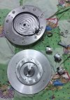
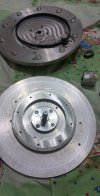
It’s actually a turntable mechanism where the DUT normally rotates. I’m trying to adapt it for HALS by essentially flipping the mechanism upside down and swapping the lower and upper parts. This allows me to keep the DUT stationary while using the rotating part as a support/interface for the microphone arm.
I’m still working on the details to make it compatible with the current HALS concept and HALS Studio.
I made the gear teeth myself rather than using a ready-made gear ring. The rotation is driven by a stepper motor and a timing belt.
So basically, I’m using the turntable mechanism “upside down” or in reverse: instead of rotating the DUT, the DUT stays fixed and the rotating mechanism becomes the motion platform for the microphone arm. The controller is already Aurduino and GRBL. This turntable used to be working with Clio for directivity plos automated measurements.
These are a few photos of the turntable mechanism I’m using as the basis for developing a HALS-compatible robot. Along this path, I’m trying to see if the overall robot structure can be made much simpler and more affordable while still maintaining good accuracy and repeatability.
 

Attachments

  • 0.PNG
    0.PNG
    50.1 KB · Views: 66
  • 2(1).PNG
    2(1).PNG
    85.2 KB · Views: 69
Congratulations are in order! This is an impressive accomplishment.

That said, and at the risk of taking the air out of your sail, do you know if you are clear of any patents Klippel may have in this regard? I ask because the original threads we had here proposed very different approaches to mechanics of the robot. Here though, what you are showing remarkably similar to Klippel NFS. Individuals making the device and using it purely for personal application is likely fine. But if they use it commercially in any manner (e.g. reviews), or sites hosting it, may be problematic. I know I don't want to be at the receiving end of a "take down" notice from Klippel especially when some of us have so extensively benefited from their commercial product.
 

HALS - Holographic Acoustic Loudspeaker Scanner​

After more than a year of development, testing and discussion, we believe HALS has reached the point where it can be presented as a usable project rather than only as a development journey.

HALS is, in essence, a DIY alternative to a Klippel-style Near Field Scanner: an automated system that measures a loudspeaker at many positions in the near field, then uses spherical harmonics to reconstruct a continuous three-dimensional model of its sound field.

This “holographic” model has two major advantages over a conventional horizontal or vertical microphone sweep:
  • It can separate the loudspeaker from the room’s influence, providing effectively anechoic measurements.
  • The reconstructed sound field can be evaluated at many locations in three dimensional space - from only 5 cm from a port, where cabinet leakage and local behaviour can be examined, to a position 50 metres away for evaluating true far-field performance.
HALS is an independent community driven project and is not affiliated with Klippel.

The project grew primarily out of collaboration between Dimitri, Tom and Jan, as well as lengthy and productive discussions with many users here and on DIY-Audio.com. The original development threads contain a great deal of background, experimentation and problem-solving, but they have inevitably become rather long.

This thread is intended to provide a cleaner introduction to the HALS system as it exists today and a central place for new users.

View attachment 560768

What does HALS do?​

HALS moves a measurement microphone through a cylindrical cloud of points around a stationary loudspeaker. At every position, it plays a sine sweep and records the loudspeaker’s impulse response. Typical measurement grids contain between 500 and 2,000 points.

The resulting collection of measurements is processed in HALS Studio, where the measured sound field can be reconstructed and analysed. HALS Studio can also generate FRD files and impulse responses for use in other software.

In practical terms, the complete workflow is:

  1. Mount and align the loudspeaker, then home the scanner.
  2. Tell the software the approximate size and position of the loudspeaker by jogging the microphone to key reference points, such as the baffle edge and tweeter.
  3. Let the software automatically generate a measurement-point cloud containing the chosen number of points.
  4. Let the scanner record an impulse response at every position. Depending on the grid and measurement settings, this typically takes between one and four hours, but the process is automated.
  5. Process the resulting measurement set in HALS Studio.
  6. Explore the response and directivity by interacting with the reconstructed sound field in 3D, placing virtual microphones and using the available analysis tools.
  7. Export plots, frequency responses, impulse responses and other results for further use.
HALS is not intended to be a direct copy of a commercial scanner, and it comes with no guarantees of accuracy or support. It is a practical DIY implementation based on accessible components including extensive use of 3D printing, open-source software and documented methods.

The documentation is still a significant area of ongoing work and will continue to improve.

View attachment 560767

The three parts of HALS​

1. Measurement and scanner-control software​

The acquisition software controls the robot, generates the measurement grid, handles audio playback and recording, and manages the complete automated scanning sequence. It produces measurement-session folders that can be opened directly in HALS Studio.

The desktop application includes:

  • Audio-interface and channel configuration
  • A cylindrical measurement-grid generator
  • Scanner calibration, homing and manual jogging
  • Automated measurement runs
  • Multiple-sweep averaging
  • Dual-channel capture for timing alignment
  • Farina-style exponential-sine-sweep deconvolution, separating the linear and nonlinear components of the impulse response
  • Live impulse-response and frequency-response displays
  • A mock mode for exploring the workflow without connected hardware
Windows installer:
Release v0.3.0 — TomKamphuys/NFS

Source code and documentation:
https://github.com/TomKamphuys/NFS

View attachment 560770
View attachment 560771

2. HALS Studio​

HALS Studio is the companion desktop application for processing and analysing the measurements made by the scanner.

Its workflow is organised into three main workspace areas:

  • Process — prepares the measurement set and performs the sound-field processing.
  • Analysis — provides advanced tools for evaluating the response, directivity and time-domain behaviour of the reconstructed sound field.
  • Export — generates FRD files and impulse responses at specified virtual-microphone positions for use in other applications, such as VituixCAD and REW.
Windows installer:
HALS Studio initial release

Source code and documentation:
https://github.com/dfapinov/HALS-Studio

Short HALS Studio tutorial:

Process:
View attachment 560775

Analyze:
View attachment 560772

Analyze:
View attachment 560773

Export:
View attachment 560774

3. Scanner mechatronics​

The physical scanner uses a rotating arm carrying a microphone assembly that can move both radially and vertically. In other words, it uses a cylindrical kinematic system. The device under test stands on a central platform and does not rotate.

The published design uses:

  • A steel tripod and central pillar
  • Standard aluminium profiles and assembly parts
  • Stepper motors and geared stepper motors
  • A BTT 3D-printer motion-control board running GRBLHAL firmware
  • Timing-belt-driven rotary and linear axes
  • Commonly available bearings, shafts and other mechanical parts
  • Approximately 80 3D-printed components
The present machine has an enclosing diameter of approximately 2.7 metres and a height of approximately 2.3 metres. Other builders could reasonably use different radial- and vertical-axis lengths to suit their available space and measurement requirements.

The mechatronics repository contains the Fusion 360 model, STEP files, bills of materials, design decisions, photographs and construction information for the main assemblies.

Hardware repository:
https://github.com/JanRSmit/HALS-Mechatronics

Jan's Scanner Build:
View attachment 560776

Getting started​

If you are mainly interested in understanding the workflow, both HALS Studio and the scanner-control software can be explored before building the complete robot. The acquisition software includes a mock mode, allowing a measurement run to be rehearsed without connected hardware.

A practice dataset for analysis and export is also available:
PRACTICE DATASET - Elac Debut 2.0

Its results can be compared with independent measurements published by >ASR< and >Erin’s Audio Corner<.

However, a more robust validation is to compare the HALS prediction against a direct measurement of the DUT at a position that was not part of the input dataset.

View attachment 560838
The measurement point shown above was not included in the HALS input data. The HALS model was used to predict the complete response at this position, which was then compared with a direct in-room measurement at the same coordinates. Some differences in smoothing remain visible as HALS uses Frequency dependant Windowing.

The download does not contain the complete input dataset of almost 2,000 impulse-response WAV files, as these require several gigabytes of storage and are impractical to host indefinitely. Instead, it contains the preprocessed holographic model—the _coefficients.h5 and _project.json files—which can be opened in HALS Studio.

For an actual scan, the main requirements are:

  • A completed scanner
  • A measurement microphone
  • An audio interface with ASIO support and at least two input and two output channels (Focusrite Scarlett 2i2, MOTU M2, Behringer UMC202 etc..)
  • A power amplifier and loudspeaker under test, or an active loudspeaker
  • A Windows 10 or Windows 11 computer connected to the audio interface and motion controller
The HALS Control software can run on a relatively low-powered computer, as it only needs to control the scanner position and play and record audio.

Processing in HALS Studio requires a reasonably modern system because the computational load can be significant and the application uses hardware-accelerated graphics. Modern integrated graphics should be sufficient.

Project status​

HALS should still be regarded as a developing DIY project, but the complete chain is now present:

  • A working and documented scanner
  • Automated measurement software
  • A graphical processing and analysis application
  • Published source code, mechanical models and documentation
The original scanner has been in practical use for a substantial period and has been used to develop and test the present software workflow.

There will certainly be further improvements, additional documentation and lessons learned from other builds. Feedback, test results, bug reports and contributions are therefore very welcome.

Links​

Measurement and scanner-control software:
https://github.com/TomKamphuys/NFS

Processing, analysis and export software:
https://github.com/dfapinov/HALS-Studio

Scanner design and mechatronics:
https://github.com/JanRSmit/HALS-Mechatronics

PRACTICE DATASET - Elac Debut 2.0
https://drive.proton.me/urls/0RZGWMYY6R#D2XFbyG3kUyg

HALS Studio tutorial video:

Original DIYAudio development thread:
https://www.diyaudio.com/community/threads/klippel-near-field-scanner-on-a-shoestring.318151/

Original ASR development thread:
https://www.audiosciencereview.com/...ner-the-mathematics-and-everything-else.9970/

We hope to welcome you aboard the HALShip!
Great stuff. So when do we start the DIY Allcubierre Drive thread?
 
This is indeed impressive work. Assuming it is clear of Klippel IP infringement, it could also have applications in RF & microwave antenna measurement. A small market, but perhaps worth a look.
 
If you ever need help with software development, feel free to reach out. I have experience in low latency programming, particularly in developing high performance math libraries. Over the past three years, I have been developing one of the fastest x86 FFT libraries available.(completely open source, MIT license)

If you need some help on a project, I’d be happy to contribute for free. We can discuss the details and see if my experience could be useful.
 
Congratulations are in order! This is an impressive accomplishment.

That said, and at the risk of taking the air out of your sail, do you know if you are clear of any patents Klippel may have in this regard? I ask because the original threads we had here proposed very different approaches to mechanics of the robot. Here though, what you are showing remarkably similar to Klippel NFS. Individuals making the device and using it purely for personal application is likely fine. But if they use it commercially in any manner (e.g. reviews), or sites hosting it, may be problematic. I know I don't want to be at the receiving end of a "take down" notice from Klippel especially when some of us have so extensively benefited from their commercial product.

Amir, thank you very much for raising this point. I really appreciate you taking the time to mention it, and I completely understand your concern.
Actually, this is something I have been thinking about as well. The mechanical architecture of the HALS scanner does look remarkably similar to the Klippel NFS, so I agree that the patent situation should be taken seriously, especially if a project like this is ever used commercially or distributed publicly as a finished product or a kit to be assembled.
I did some initial digging into the Klippel NFS-related patents, and there is an interesting distinction that I think is worth making.
From what I can see so far, the patent is not simply claiming the general idea of moving a microphone around a loudspeaker with a positioning system. The claims appear to cover a much more specific combination of measurement and processing techniques, including field separation, direct/secondary wave separation, extrapolation, adaptive scanning, certain coefficient-selection methods, and related processing steps.
The patent description does, of course, describe embodiments using a positioning system with R/Z/Phi-type motion, which explains why the mechanical similarity is so noticeable. But the specific mechanical geometry itself doesn't seem to be the entire scope of the claims.
That said, I'm definitely not treating this as a legal conclusion. A proper freedom-to-operate analysis would require looking at the complete patent families, their prosecution history, and their current status in each relevant country.
 
Back
Top Bottom