• WANTED: Happy members who like to discuss audio and other topics related to our interest. Desire to learn and share knowledge of science required. There are many reviews of audio hardware and expert members to help answer your questions. Click here to have your audio equipment measured for free!

Fun with vinyl measurements

Risto_H

Member
Joined
Jul 30, 2019
Messages
20
Likes
53
Can the schematic be shared here too?
In principle, yes but I think that would better in some other thread or what do you think?

I'm currently learning how to use the QA403 analyzer to reproduce what @amirm is doing with the AP. When I get a good graph with comparable Sinad readings, I will post the results here. So far it looks like the RIAA response of my design might be unmatched but it lags a bit behind the best in S/N ratio. The preliminary distortion readings with MM input and 5 mV input level are not too bad: < 0.0005 %. MC input adds a bit of distortion but nothing to worry about. There's a separate 20 dB gain stage that activates when MC input is selected.

I have so far built four of these and all of them perform quite the same although I did have to change some of the RIAA chain capacitors to achieve that. The capacitors had been knocked out of their specs due to hand soldering with lead-free solder.

IMG_20220204_203510.jpg
 

Risto_H

Member
Joined
Jul 30, 2019
Messages
20
Likes
53
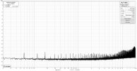
Well, here's the SINAD graphs of my RIAA from both MM and MC inputs and lowest gain setting. I use 5 mV input signal for MM and 0.5 mV for MC (as used in the reviews here).

I find < 40 dB of gain something that would not be normally needed with MM and that's why the four selectable gain steps are 40 dB, 43 dB, 46 dB and 48 dB. MC signal path just adds another 20 dB on top. In the case of MM input, the 1st stage is TI OPA1656 which has very low distortion and current noise, whereas voltage noise is not the lowest possible. However, with audio analyzer, source resistance is very different from a typical MM cartridge which favors input stages that have low voltage noise but may have poor current noise. In the real world situation, low current noise is very important since otherwise MM cartridge inductance and resistance boost noise floor up quite a bit due to current noise of the input stage. With SINAD reading of ~72 dB, my design would be right in the middle of the chart presented here.

As you can see, the SINAD figure is noise dominated and in this case, particularly noise < 300 Hz. This is what OPA1656 datasheet also shows for voltage noise. A-weighting increases the SINAD figure to 86 dB at 5 mV input.

Measuring MC input noise with an analyzer is a whole different story. Since both typical analyzer and MC cartridges are low impedance sources, your measurement results are very much in line with the real world performance. The challenges with MC lie totally elsewhere and that is external noise. When input signal is only 0.5 mV or 500 uV, noise components could be 80 dB below measurement source generator (or even almost 90 dB below like in the example here) and would still show clearly above noise floor. That is 0.5 mV / 10000 = 50 nV! In the case of my measurement setup with QA403, I could not yet get it perfected in my hobby room. Clearly the system picks up weak noise signals from nearby consumers of electricity that appear as 150 Hz noise spikes and other higher harmonics of 50 Hz AC (I'm located in Finland where AC is 230 V / 50 Hz). These noise signals change size if I move the setup around but fortunately they don't affect the SINAD reading much. In this case, the MC input SINAD is ~70 dB which I believe is pretty good.

I'm pretty happy with the result and performance, especially distortion figures and RIAA EQ accuracy are good. Additionally there's no electrolytic caps that would eventually wear down. Note that the left channel shows a bit elevated distortion but this is not real, it is caused by the QA403 output buffer which for some reason has slightly better performance in the right channel. Swapping the QA403 outputs also swaps the distortion figures so it is actually the analyzer that limits distortion performance slightly.

SINAD from MM input:

MM THD_N -60 dB atten cable compensated 00 gain Serial# 000.png


SINAD from MC input:

MC THD_N -60 dB atten cable compensated 00 gain Serial# 000.png
 
OP
Balle Clorin

Balle Clorin

Major Contributor
Joined
Dec 26, 2017
Messages
1,332
Likes
1,209
The effect of stylus drag when lowering pickup onto record..
(JJ Cale - "Anywhere the the wind blows", middle of track)
1656826137205.png


Please notice the DIN W&F numbers for the two tests... DIN filtering "lies" quite a bit.

An here speed stability with record in groove(music playing), higher peak wow , but it may also be just day to "bad-day" variation. Turntable varies between 0.09 and 0.11% peak variation
1656831339894.png
 
Last edited:

USER

Addicted to Fun and Learning
Forum Donor
Joined
Mar 30, 2019
Messages
939
Likes
1,553
I just finished putting together the KA Electronics Flat Moving Magnet Phono Preamp and am using it hooked up to the E1DA Cosmos ADC. These very cursory measurements are making me laugh. The numbers will be even better when my Denon DP-35F is modified to be balanced and I adjust a few things. Again, this is just a quick test to see if it works. Over-engineering is fun!

Before (Denon - Manley Chinook [45dB Gain] - miniDSP SHD - PC):
35F MANLEY 45dB (256) RUNNING.jpg


Edit: Added Parks Audio Puffin for comparison. It should be mentioned that the first is a RIAA phono preamp and the last two don't have it without it (I will apply RIAA digitally), so some differences can be explained by that.

Before (Denon - Parks Audio Puffin* [25dB Gain] - miniDSP SHD - PC):

* In Line-Out mode w/o RIAA

35F Puffin Flat (512 25dB).jpg


Edit 2: Balanced (Denon* - Flat MM [28dB Gain] - E1DA Cosmos [1.7V] - PC):

*Both turntable and phono preamplifier are now balanced.

DP-35F - FLAT MM - E1DA COSMOS.jpg
 

Attachments

  • FLAT E1DA 512 1.7V RUNNING.jpg
    FLAT E1DA 512 1.7V RUNNING.jpg
    538.4 KB · Views: 118
Last edited:

JP

Major Contributor
Joined
Jul 4, 2018
Messages
2,292
Likes
2,468
Location
Brookfield, CT
A convert!
 
OP
Balle Clorin

Balle Clorin

Major Contributor
Joined
Dec 26, 2017
Messages
1,332
Likes
1,209
Trying to measure HTA alignment via TACET test record
What does this tell me about the HTA aligment... ( Yes I see it is not perfect, higher level on right channel with mono out of phase/vertical modulation) but should the alignment go clockwise or anti-clock wise?
AT-OC9ML/II = microline stylus

IN -phase (lateral) leveles are L/R -13.16/-13.18 db
Out of phase(vertical) levels are -14.2/-12.9 db
According to TACET perfect alignment should give no change or on levels or equal levels, whell I do not have that , The test record does not describe any corrective actions, kind of unhelpful

EDIT:
In phase has L/R distortion 2 harmonic of 0.19/0.40%
Out of phase has L/R distortion 2 harmonic of 0.28/0.21%

1658129372698.png


1658129431417.png


9
For the VTA intermodulation test( 341+659Hz tones 1:1= 1000hz IMD product) I tried both with a 2mm mat on platter and without( to emulate changing tonearm VTA)
Better with NO mat, so I need to raise my tonearm


1658130488598.png


1658130581783.png
 
Last edited:
OP
Balle Clorin

Balle Clorin

Major Contributor
Joined
Dec 26, 2017
Messages
1,332
Likes
1,209
Played with arm height and got minimum intermodulation distortion down from 1.5% to 0.8% on the Tacet test record. ended up with 4mm higher arm end and 1degree downward tilt on arm
1659357539933.png
 

levimax

Major Contributor
Joined
Dec 28, 2018
Messages
2,388
Likes
3,515
Location
San Diego
Played with arm height and got minimum intermodulation distortion down from 1.5% to 0.8% on the Tacet test record. ended up with 4mm higher arm end and 1degree downward tilt on arm
View attachment 221637
Wow 4 mm is a lot! So much for the worry about Dynaflex vs 200 gram record thickness which is only a few tenths of mm difference.
 
OP
Balle Clorin

Balle Clorin

Major Contributor
Joined
Dec 26, 2017
Messages
1,332
Likes
1,209
Not much actually, 4mm is only 1 degree. And cartridge VTA/SRA misalignment errors are easily +/- 1 degre that is A span of 8mm.
Hardly any difference in IMD% on 180 grams vs 120gram records.
 
Last edited:

levimax

Major Contributor
Joined
Dec 28, 2018
Messages
2,388
Likes
3,515
Location
San Diego
Not much actually, 4mm is only 1 degree. And cartridge VTA/SRA misalignment errors are easily +/- 1 degre that is A span of 8mm.
Hardly any difference in IMD% on 180 grams vs 120gram records.
When you look at the new alignment does it visually look "tail up" or "tail down" or level?
 

USER

Addicted to Fun and Learning
Forum Donor
Joined
Mar 30, 2019
Messages
939
Likes
1,553
Quick question: is a 1kHz signal OK to use with Wow & Flutter measurements? I found a JVC TRS-1002 test record and the 3kHz signal is way off, but the 1kHz is giving me what seems to be a reasonable response, even if off-centered a bit. Any reason to not use it for a wide view like this:

1k.png
3k.png

This turntable has come a long way and I think I am done rebuilding it. Unfortunately, I ruined my working Tacet test record andI have not been able to find a suitable replacement since.

Denon DP-30L II · Tacet.png
 

atmasphere

Addicted to Fun and Learning
Technical Expert
Audio Company
Joined
May 26, 2021
Messages
508
Likes
793
Has anyone done a test showing distortion vs 'correct' loading vs no load (47K stock) when using a MM cartridge?

To my understanding the loading affects distortion of the cartridge output at audio frequencies (unlike a LOMC cartridge) due to the much higher inductance.
 
OP
Balle Clorin

Balle Clorin

Major Contributor
Joined
Dec 26, 2017
Messages
1,332
Likes
1,209
Quick question: is a 1kHz signal OK to use with Wow & Flutter measurements? I found a JVC TRS-1002 test record and the 3kHz signal is way off, but the 1kHz is giving me what seems to be a reasonable response, even if off-centered a bit. Any reason to not use it for a wide view like this:

View attachment 221733View attachment 221734
This turntable has come a long way and I think I am done rebuilding it. Unfortunately, I ruined my working Tacet test record andI have not been able to find a suitable replacement since.

View attachment 221737
How do you generate these polar plots?
I had no problems buying a Tacet test record from Amazon
Wow&flutter on 1000hz is just fine
1659445963486.png
 

levimax

Major Contributor
Joined
Dec 28, 2018
Messages
2,388
Likes
3,515
Location
San Diego
Did you see the photo in my post above?
Yes the photo's are great but I am not completely sure how they correlate to an old fashioned "eyeball" of "tail up" or "tail down" relative to the bottom of the cart. Assuming the cart is mounted square to everything I guess it would be a slight "tail down" but I am not sure from the photo's as everything seems to be angled down.. Sorry if I am being dense.
 

USER

Addicted to Fun and Learning
Forum Donor
Joined
Mar 30, 2019
Messages
939
Likes
1,553
How do you generate these polar plots?
I had no problems buying a Tacet test record from Amazon
Wow&flutter on 1000hz is just fine
View attachment 221916
I've returned many, many Tacet records. Was only able to find one that worked properly and I ruined it unfortunately. I'll try out the 1k signal on it but I am now guessing it looks better here because of resolution and scale.

Figure 2022-08-01 195147.png
Figure 2022-08-01 194849.png


3Hz vs 1Hz increments. Not saying this isn't useful for restoration work, but I wish there was a dependable and available wow and flutter test record.

The script for the plot is on this very thread.
 

Attachments

  • 30L II - L 3k.png
    30L II - L 3k.png
    1.1 MB · Views: 39

JP

Major Contributor
Joined
Jul 4, 2018
Messages
2,292
Likes
2,468
Location
Brookfield, CT
I've returned many, many Tacet records. Was only able to find one that worked properly and I ruined it unfortunately. I'll try out the 1k signal on it but I am now guessing it looks better here because of resolution and scale.

View attachment 221923View attachment 221924

3Hz vs 1Hz increments. Not saying this isn't useful for restoration work, but I wish there was a dependable and available wow and flutter test record.

The script for the plot is on this very thread.

I've had no luck with them either.
 
OP
Balle Clorin

Balle Clorin

Major Contributor
Joined
Dec 26, 2017
Messages
1,332
Likes
1,209
Yes the photo's are great but I am not completely sure how they correlate to an old fashioned "eyeball" of "tail up" or "tail down" relative to the bottom of the cart. Assuming the cart is mounted square to everything I guess it would be a slight "tail down" but I am not sure from the photo's as everything seems to be angled down.. Sorry if I am being dense.
Pickup is to the left ang arm pivot to right . The white line on the SME V arm can be compared directly with the transparent levelblock orange lines, so the arm slopes down towards the cartridge . So the carts needle end is lower than the wire end
 
Top Bottom