- Joined
- Nov 29, 2020
- Messages
- 184
- Likes
- 50

Thanks. Since I already run ARC room correction, I definitely wanted something passive if possible. A miniDSP would add an extra ADC conversion. So far, I am happy with the FMOD as well.I've used both the inline ones and adjustable one. Very happy with both.
Currently running a MiniDSP Flex (wanted balanced connections and moved to a 2.2 system I wanted DSP and lots of tuning for).
This thread reminded I have the adjustable FMOD set up in my garage system. But I have a currently unused minidsp DDRC-24 laying around. Obviously the garage "needs" DSP too and I now know what today's project is. Oh wait I have a Topping E30 laying around too. Darn it. Today's project is now MiniDSP vs DAC + FMOD. It's a sickness. A fun sickness though.Thanks. Since I already run ARC room correction, I definitely wanted something passive if possible. A miniDSP would add an extra ADC conversion. So far, I am happy with the FMOD as well.
Really? I didn't catch that in the product blurb. I'd love to see THAT thing measured, see if the slope and frequencies are accurate at all. (Hint to @amirmPFmod, it's an 18dB/oct
") ).
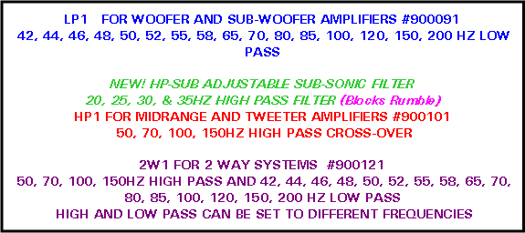
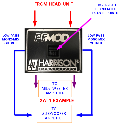
).I Use this from them. It works well and I can select my frequency crossovers. I run a tri-amped systemDoes anyone have first hand experience with these?
https://www.hlabs.com/products/crossovers/index.htm
Do they actually work as advertised? Any attenuation, distortion, noise issues?
I am mainly interested in an inexpensive way to filter out bass at line level (RCA) going from preamp to my amp and bookshelf speakers.
Also, am I right to assume that a typical 100 Hz high pass filter with a 12 dB/octave slope is already down 3 dB at 100 Hz? Trying to decide if a 70 Hz one or a 100 Hz one would be better for my PSB Alpha B speakers (5.25" drivers), which are rated ±3dB from 65-21,000Hz.
Thanks!
You have to include the upwards and downwards impedance as well.Could someone on this scientific forum at least verify the schematic?
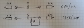
So how to do it? Simple inline hipass filter for god's sake. I don't even ask for 18dB/oct or 24dB/oct . Impedances 20 Ohms (Pre) and 100k Ohms (Amp).You have to include the upwards and downwards impedance as well.
In pre's case it may not be the same as levels change (depending on how it makes VC) .
Below is from the Harrison Lab web site (source).So how to do it? Simple inline hipass filter for god's sake. I don't even ask for 18dB/oct or 24dB/oct . Impedances 20 Ohms (Pre) and 100k Ohms (Amp).


Didn't read this thread carefully enough. Not knowing that you simply asked for the R & C values of a high pass first order RC filter. Here is the frequency response plot:Right, they provide little information because they want to charge 28 USD for a cap and resistor

Thanks a lot,Choose C = 0.47 μF. As fc = 70 Hz, the value of R = 4837.54 Ω.
Since R is R2 parallel with R_load, therefore R2 = 1 / (1/R - 1/R_load) = 1 / (1/4837.54 - 1/100000) = 5083.45 Ω
Round to the nearest available value = 4.7 kΩ.
Solution: R_filter = 4.7 kΩ; C_filter = 0.47 μF
 www.digikey.com
1. using other RC combinations, for ex. R_filter = 22.7 kΩ; C_filter = 0.1 μF (or) R_filter = 294 kΩ; C_filter = 7733 pF
2. using RL filter (instead of RC), for. ex. R=10Ω; L=22mH
3. using LC filter (instead of RC), for ex. L= 50mH; C=100uF
When implemented properly (by choosing the appropriate values with the appropriate type of components), they should sound the same.Is it any "sonical" benefit using more expensive LC instead of RC? I could use 50mH air coil and 100uF mkp cap (actually I got 2 of them). I don't understand why in RC filter coil (large inductance) can be replaced with just a resistor (with negligible inductance)???
Most of the cost is putting the components in an enclosure which connects to RCA male plugs on each side.Right, they provide little information because they want to charge 28 USD for a cap and resistor