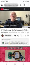
This is a review and description of a FE-6J1-2 Tube preamplifier kit which can be ordered from many internet stores, e.g. AliExpress. I bought mine from a local store at about $18.

It is a simple circuit that is powered from external 12Vac power supply. It uses 6J1 tubes that are able to work at low 56Vdc voltage. This is obtained by voltage doublers that are a part of the circuit on the PCB. The preamp can be ordered as an assembled PCB or as a kit with a PCB and parts included, for DIY soldering.
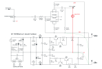
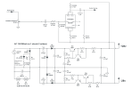
I soldered the board and put it into a case from Douk audio MC103 switch, which I have not been using anymore. Below you can see the photos of the assembled board and of the board in the case, as well as the schematics supplied with the kit.
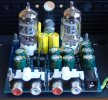
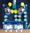
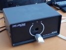
After soldering has been completed, the preamp has worked immediately, without issues. So I can show some usual measurements. There have been no parameters mentioned from the supplier, except for schematics, BOM and notes about the 12Vac power supply voltage.
Measurements – general
All measurements were done with a 100 kOhm load, as it is a tube preamp with high output impedance. I am using my unity gain buffer (op-amp + BUF634T) with 100k input impedance for such purposes, placed before the Cosmos ADC input. DAC used was Topping DX5 driven via optical cable, to avoid ground loops.
I am very sorry but I made the measurements with 1 kOhm load instead of 100 kOhm. Below are corrected measurements.
1. Input impedance
Input impedance is 50 kOhm and it is defined by the volume pot placed just at the preamp input.
2. Output impedance
Output impedance is high, 4.7 kOhm. So it has to be loaded by 50 kOhm or more, otherwise the preamplifier gain will be reduced. However, the preamplifier tolerates 10 kOhm load, with significant loss of gain and some drop at lowest frequencies.
3. Voltage gain
16.5 dB when loaded with 100 kOhm. The measurements below are made with volume pot set to gain +14dB
4. Frequency response

At the high frequencies we can see the effect of volume pot set to +14dB. But it is still very good.
5. THD and THD+N at 1V

Though we usually measure THD+N at higher output voltage, this tube preamplifier has very high distortion at higher output level. So I am posting the spectrum at about 1V output. Distortion vs. output voltage will be shown later.
We have about 1% distortion at 2V. Though there is a filter with capacitance multiplier in the on-board power supply, the power supply ripple rejection is poor and we can see many mains related spectrum lines.
6. THD and THD+N vs. output voltage at 1kHz

Again, the result is poor. THD+N is dominated by noise at low output voltage and above 1V it is dominated by distortion.
7. THD+N vs. frequency at 1V

Distortion vs. frequencies is flat, however very high.
Listening
When connected to my main system, the hum from the preamp is unfortunately audible. Other than that, the sound is acceptable, as human ear is quite tolerant to non-linear distortion.
Conclusion
I cannot recommend this tube preamp for serious listening. If the goal is to learn something and try tubes and soldering, then it may have some value, regarding its low cost.
_____________________________________________________________________________________________________________________________________________________
There is a temptation to create a listening test with files recorded through this preamp, so here we go:
Test - Topping D10s/Cosmos ADC loop vs. Tube preamp (6J1) in the loop
link to the test files:
 drive.google.com
Please feel free to try the test and tell me if you hear the difference, and do not forget to post foobar abx test report.
I have also included a delta file (Deltawave difference) for you to hear how horrible is the "sound" of tube distortion in isolation. But, can you hear it when playing music?
I have also created an on-line version of the test:
 abx.funkybits.fr
It is a simple circuit that is powered from external 12Vac power supply. It uses 6J1 tubes that are able to work at low 56Vdc voltage. This is obtained by voltage doublers that are a part of the circuit on the PCB. The preamp can be ordered as an assembled PCB or as a kit with a PCB and parts included, for DIY soldering.
I soldered the board and put it into a case from Douk audio MC103 switch, which I have not been using anymore. Below you can see the photos of the assembled board and of the board in the case, as well as the schematics supplied with the kit.
After soldering has been completed, the preamp has worked immediately, without issues. So I can show some usual measurements. There have been no parameters mentioned from the supplier, except for schematics, BOM and notes about the 12Vac power supply voltage.
Measurements – general
All measurements were done with a 100 kOhm load, as it is a tube preamp with high output impedance. I am using my unity gain buffer (op-amp + BUF634T) with 100k input impedance for such purposes, placed before the Cosmos ADC input. DAC used was Topping DX5 driven via optical cable, to avoid ground loops.
I am very sorry but I made the measurements with 1 kOhm load instead of 100 kOhm. Below are corrected measurements.
1. Input impedance
Input impedance is 50 kOhm and it is defined by the volume pot placed just at the preamp input.
2. Output impedance
Output impedance is high, 4.7 kOhm. So it has to be loaded by 50 kOhm or more, otherwise the preamplifier gain will be reduced. However, the preamplifier tolerates 10 kOhm load, with significant loss of gain and some drop at lowest frequencies.
3. Voltage gain
16.5 dB when loaded with 100 kOhm. The measurements below are made with volume pot set to gain +14dB
4. Frequency response
At the high frequencies we can see the effect of volume pot set to +14dB. But it is still very good.
5. THD and THD+N at 1V
Though we usually measure THD+N at higher output voltage, this tube preamplifier has very high distortion at higher output level. So I am posting the spectrum at about 1V output. Distortion vs. output voltage will be shown later.
We have about 1% distortion at 2V. Though there is a filter with capacitance multiplier in the on-board power supply, the power supply ripple rejection is poor and we can see many mains related spectrum lines.
6. THD and THD+N vs. output voltage at 1kHz
Again, the result is poor. THD+N is dominated by noise at low output voltage and above 1V it is dominated by distortion.
7. THD+N vs. frequency at 1V
Distortion vs. frequencies is flat, however very high.
Listening
When connected to my main system, the hum from the preamp is unfortunately audible. Other than that, the sound is acceptable, as human ear is quite tolerant to non-linear distortion.
Conclusion
I cannot recommend this tube preamp for serious listening. If the goal is to learn something and try tubes and soldering, then it may have some value, regarding its low cost.
_____________________________________________________________________________________________________________________________________________________
There is a temptation to create a listening test with files recorded through this preamp, so here we go:
Test - Topping D10s/Cosmos ADC loop vs. Tube preamp (6J1) in the loop
link to the test files:
6J1_test.zip
Please feel free to try the test and tell me if you hear the difference, and do not forget to post foobar abx test report.
I have also included a delta file (Deltawave difference) for you to hear how horrible is the "sound" of tube distortion in isolation. But, can you hear it when playing music?
I have also created an on-line version of the test:
6J1 tube preamp vs. Topping DAC/Cosmos ADC loop · FunkyABX
Last edited:


 .