

Safety Risks and Hazardous Waste
"The limited energy in capacitors (E = ½ C V²) restricts the duration of the shock, even if there are no circuit breakers to trip. The shock current will be limited by the body resistance, and the duration of the shock will be characterized by the time constant (τ = R C)."[1]
Electronics often carry warnings against opening their enclosures. Even after a device is turned off and unplugged, internal capacitors and batteries can store electric charges. AC causes significantly higher risk of muscular tetany and cardiac arrhythmia than DC, under comparable conditions. Protective devices such as GFCIs or RCDs help mitigate this by rapidly cutting fault current duration. Digi-Key Electronics has calculators for safely discharging capacitors with a resistor that has the required wattage.[2][3][4] Digi-Key Electronics warns against discharging capacitors with a screwdriver, since the resistance near zero produces a high-current discharge instead of a safe RC time constant with a resistor.[5] The resistor power rating is important for capacitors with many joules, based on the instantaneous power P = V² / R. Extra-low voltage (ELV) is defined by contact voltage thresholds of ≤50 V AC and ≤120 V DC, where fault protection might not be needed (IEC 61140). Converting the capacitance and voltage of a capacitor to joules is useful to know whether there is a safety hazard. Stored energy of >1.0 J if ≥100 V and >100 J if <100 V are standardized electric shock or thermal hazard thresholds (NFPA 70E).
Electrical safety thresholds should not be interpreted as universal, physiological safety limits. A capacitor containing several joules or more can be a significant hazard, but the physiological effect of electric shock depends on voltage, current, resistance, duration, frequency and electrophysiological path. The energy initially stored in a capacitor is useful for identifying potentially hazardous circuits, but it does not by itself determine whether a particular discharge will cause ventricular fibrillation. Even a shock that does not cause a severe, physiological effect can trigger a startle reflex. The resulting involuntary movement can cause secondary injuries such as falls, burns or contact with moving machinery. More severe shocks can interfere with voluntary muscle control, making it difficult or impossible to release the conductor. Experimental studies have identified ranges of current in which involuntary muscle contraction can interfere with a person's ability to release an energized conductor. These values are commonly called let-go currents. They are not universal safety limits, since the response depends on varying factors, such as contact resistance, duration and the physical condition of the person.[6]
The electrolyte in capacitors can be toxic, irritating or corrosive. Soldering flux is a considerable problem with inhalation or skin contact, because of asthma and dermatitis. Hazardous lead vaporization requires about 450 °C or higher, which is more than hand soldering temperatures, but lead ingestion from solder should be prevented with hand hygiene. Recommended precautions for electronics labs include soldering fume extraction, safety glasses, gloves and lab coats with ESD protection.[7][8] Common electronics lab waste, such as spent isopropyl alcohol, lead solder dross, flux-contaminated materials and leaked capacitor electrolyte are disposed of as hazardous under environmental regulations (like the EU Waste Framework Directive).[9][10][11]
Electrotechnical Concepts in Practice
"The reader is cautioned against interpreting the differences between the voltage values as a true index of the relative hazard between alternating current and direct current. Current is the proper criterion of electric shock intensity, and the hazard from the proposed reasonably safe voltages would be greatly increased if contact occurred at locations where the skin was lacerated or if local high current densities produced material breakdown of the skin. Currents of the let-go level are more than sufficient to produce very serious burns."[12]
SI (metric) prefixes are used to express physical quantities, for example megahertz (MHz = 10⁶ Hz), kilovolts (kV = 10³ V), milliohms (mΩ = 10⁻³ Ω), microamperes (μA = 10⁻⁶ A), nanohenrys (nH = 10⁻⁹ H) and picofarads (pF = 10⁻¹² F). Electrostatic discharge (ESD) is a significant risk for sensitive components (like transistors and integrated circuits), because electrostatic charge in the kilovolt range often builds up with the triboelectric effect, which can cause dielectric breakdown or junction failure. The human body has very small capacitance C in the picofarad range, so electric charge Q causes very large voltage V = Q / C. The resistivity of blood is approximately 100 Ω cm, and 800 Ω cm for muscle tissue.[13][14] Total impedance of living human beings can electrophysiologically be modeled as approximately 2 kΩ to 4 kΩ, under average AC mains conditions (IEC 60479-1).
Multimeters are used for measuring voltage in capacitors. However, LoZ (low-impedance) mode should not be used to discharge high-energy capacitors. LoZ mode is designed to eliminate phantom voltage caused by capacitive coupling between conductors. Discharging stored DC through a meter can exceed thermistor limits or blow protective fuses. SI units are used for dimensional analysis in equations. In the Yamaha M-2 power amplifier for example, the power supply capacitors are both rated for E = ½ C V² = ½ (22 000 μF) (100 V)² = ½ (0.022 F) (100 V)² = 110 J = 110 W s. Aluminum electrolytic capacitors have a finite service life that depends on varying factors, such as operating temperature, ripple current, applied voltage and construction. Manufacturers commonly specify an expected lifetime under particular operating conditions rather than a universal expiration date.[15][16] Physical stress or severe vibration applied to soldered components can crack solder joints, tear copper pads from the PCB (printed circuit board) or break internal bonds. Film capacitors generally have a very long service life, but their relatively low ESR (equivalent series resistance) can cause circuit instability, such as ringing or oscillation in power supplies and feedback loops without the resistive damping of electrolytic capacitors.[17]
Measurement Technique and Specifications
"For aluminum electrolytic capacitors, the capacitance is measured under the standard measuring conditions of 20°C and a 120Hz AC signal of about 0.5V. Generally, as the temperature rises, the capacitance increases; as the temperature decreases, the capacitance decreases (Fig. 7). With a higher frequency, the capacitance is smaller; with a lower frequency, the capacitance is larger (Fig. 8)."[18]
Capacitance, dissipation factor and leakage current are measured to determine whether a capacitor works.[19][20] Always discharge the capacitor first if required by the measurement equipment. Non-polarized (bipolar) electrolytic capacitors are designed to tolerate AC, but only with the manufacturer's voltage, frequency, ripple current and temperature ratings. Ripple current produces internal heating, primarily through ESR, and power dissipation can be estimated with P = I² R. Excessive heating accelerates electrolyte evaporation or other aging mechanisms, reducing the overall service life. Every 10 °C increase in operating temperature is estimated to shorten the service life of aluminum electrolytic capacitors to half, because of the Arrhenius equation. Aluminum electrolytic capacitors will lose their electric charge with time, but there is dielectric absorption that brings previous charge back, sometimes up to about 10%. Long-term storage of aluminum electrolytic capacitors can increase leakage current, where the dielectric requires reforming, which should be performed with the procedure of manufacturers. If the rated voltage (also called the working voltage) is not applied to the electrolytic capacitor for many years, then the dielectric strength degrades.[21] A discharged capacitor initially appears to have a relatively low resistance before the indicated resistance increases as the capacitor charges from the applied test current, although this test cannot determine precise capacitor conditions.
The standardized measuring frequency for capacitance of electrolytic capacitors is 100 Hz or 120 Hz, at a temperature of 20 °C (IEC 60384-1).[22] Film capacitors are often measured at 1 kHz. MKT, MFP and MKP film capacitors with a rated capacitance ≤1 μF have additional measuring frequencies of 10 kHz or 100 kHz for dissipation factor.[23] When replacing a capacitor, the replacement should normally have the same nominal capacitance and the same or higher voltage rating. An ordinary capacitor should not be confused with an X/Y safety capacitor.[24] This also depends on finding the right temperature rating, ripple current rating, dissipation factor and physical dimensions, including lead spacing for the replacement. LCR meters (or software like Room EQ Wizard) apply an AC test signal. LCR measurements of a component connected to a circuit can be misleading. Verification of specifications also gives an impression of authenticity if an authorized distributor was not used. However, there can still be defects because of the acceptance quality limit (ISO 2859-1 and JIS Z 9015-1).[25] The typical failure modes of aluminum electrolytic capacitors are short circuit, open circuit, electrolyte leakage, increase in leakage current and open vent when heat or internal pressure increases because of excessive operating voltage or ripple current.[26] Bipolar transistors (BJTs) can be tested using a multimeter with diode test mode. A conventional silicon transistor will show a forward voltage drop of about 0.6 V to 0.7 V from base to emitter and base to collector, and open loop (OL) when measured in reverse, while collector to emitter must read OL in both directions.
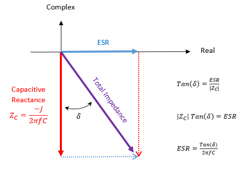
"A capacitor’s total complex impedance is represented on a real-complex plane as the vector sum of a real component, (the ESR) and a complex (reactive) component representing the ‘ideal’ capacitor that things like ESR mess up in all actual components. The angle between the total impedance and its complex component is called the ‘loss angle,’ and is a figure used to summarize the ratio between the ideal and non-ideal components of a capacitor’s overall impedance."[27]
Soldering Technique and Component Replacement
"The expected life time shall be about fifteen years at maximum as a guide in terms of deterioration of the sealant."[28]
Rosin or resin flux that is halide-free, respectively called ROL0 or REL0 is used because of chemical reactions of halides or other fluxes that are harmful for aluminum electrolytic capacitors or other electronic components (J-STD-004). Eutectic Sn63/Pb37 solder is often the best option for servicing vintage electronics, since restriction of lead in the European Union came into effect for products and spare parts originally placed on the market on July 1, 2006 or later. RoHS restricts certain hazardous substances in products. Polarized components (like electrolytic capacitors and LEDs) must be installed with the correct polarity, since reverse polarity can prevent the component from functioning or cause catastrophic failure. Applying pressure during soldering can cause excessive wear on solder pads. Movement of components during solidification disturbs the joint as it cools, producing a solder joint lacking mechanical integrity.
ELNA states that the sleeves of aluminum electrolytic capacitors should not be considered as an insulation, and that the aluminum case is connected to the cathode terminal through the electrolyte, which has uncertain resistance.[29] Surface tension, wetting and capillary action primarily determine solder adhesion, so plated through-holes can be soldered at a slight angle for better ergonomics and vision. ELNA states that the optimal dwell time during hand soldering is less than 3 seconds for electrolytic capacitors.[30] Pre-applying flux is essential for SMD drag soldering, transfer soldering or rework. However, pre-applied flux is optional for through-hole soldering using flux-cored solder. Oxidation prevents intermetallic bonding, although gold does not oxidize under normal conditions.[31] The soldering iron tip must be tinned regularly to prevent oxidation. The soldering iron tip should be set to at least 30 °C to 50 °C above the liquidus temperature of the solder, to ensure enough heat transfers into solder joints for intermetallic bonding.[32] Nichicon recommends using isopropyl alcohol for cleaning PCBs, although compatibility with electronic components varies. Capacitors directly connected in series might need voltage-balancing (bleeder) resistors in parallel across each one. Otherwise, unequal resistance or leakage current risks imbalanced voltage and overvoltage breakdown.[33]
References
[1] Scott, Mark A. "Working Safely with Hazardous Capacitors". IEEE Industry Applications Magazine (Volume 25, Issue 3, May–June 2019).
https://ieeexplore.ieee.org/ielaam/2943/8685745/8661497-aam.pdf
[2] Sculley, D. RC Time Constant. Tufts University.
https://www.eecs.tufts.edu/~dsculley/tutorial/rc/rc3.html
[3] Digi-Key Electronics. Capacitor Safety Discharge Calculator.
https://www.digikey.dk/en/resources...version-calculator-capacitor-safety-discharge
[4] Digi-Key Electronics. Time Constant Calculator.
https://www.digikey.dk/en/resources/conversion-calculators/conversion-calculator-time-constant
[5] Awalt, Ashley. How to Safely Discharge a Capacitor. Digi-Key Electronics.
https://www.digikey.com/en/blog/how-to-safely-discharge-a-capacitor
[6] Dalziel, Charles F. "Effects of Electric Shock on Man". IRE Transactions on Medical Electronics (PGME-5, July 1956).
[7] Lawrence Berkeley National Laboratory. Safe Soldering Work Practices.
https://eta-safety.lbl.gov/sites/default/files/Soldering Guidelines.pdf
[8] Massachusetts Institute of Technology. Soldering Safety and Health Guidelines.
https://ehs.mit.edu/wp-content/uploads/EHS-0167.pdf
[9] Nippon Chemi-Con. Precaution of Capacitor Disposal.
https://www.chemi-con.co.jp/en/faq/detail.php?id=29BFLER
[10] University of Cambridge. Soldering Safety.
https://safety.eng.cam.ac.uk/safe-working/copy_of_soldering-safety
[11] Farnell. Managing Solder Fume Extraction.
https://uk.farnell.com/essential-considerations-for-managing-soldering-fume-extraction-p2
[12] Dalziel, C. F. & Massoglia, F. P. "Let-Go Currents and Voltages". Transactions of the American Institute of Electrical Engineers, Part II: Applications and Industry (Volume 75, Issue 2, May 1956).
[13] Schwan, Herman P. & Kay, Calvin F. "Specific Resistance of Body Tissues". Circulation Research (Volume 4, No. 6, November 1956).
https://www.ahajournals.org/doi/pdf/10.1161/01.RES.4.6.664?download=true
[14] Rush, Stanley, Abildskov, J. A. & McFee, Richard. "Resistivity of Body Tissues at Low Frequencies". Circulation Research (Volume 12, No. 1, January 1963).
https://www.ahajournals.org/doi/pdf/10.1161/01.RES.12.1.40?download=true
[15] Nichicon. Application Guidelines for Aluminum Electrolytic Capacitors.
https://www.nichicon.co.jp/english/products/pdf/aluminum-e.pdf
[16] Parler, Sam G., Jr. Reliability of CDE Aluminum Electrolytic Capacitors. Cornell Dubilier.
https://www.cde.com/resources/technical-papers/reliability.pdf
[17] Cornell Dubilier. AC Capacitor Application Guide.
https://www.cde.com/resources/technical-papers/ACappGUIDE.pdf
[18] Nippon Chemi-Con. Judicious Use of Aluminum Electrolytic Capacitors.
https://www.chemi-con.co.jp/products/relatedfiles/capacitor/catalog/al-technote-e.pdf
[19] Parler, Sam G., Jr. Selecting and Applying Aluminum Electrolytic Capacitors for Inverter Applications. Cornell Dubilier.
https://www.cde.com/resources/technical-papers/selectinvcap.pdf
[20] Parler, Sam G., Jr. & Macomber, Laird L. Predicting Operating Temperature and Expected Lifetime of Aluminum-Electrolytic Bus Capacitors with Thermal Modeling. Cornell Dubilier.
https://www.cde.com/resources/techn...erating-Temperature-and-Expected-Lifetime.pdf
[21] Würth Elektronik. Afraid of Aging? The Effects of Time on Electrolytic Capacitors.
https://www.we-online.com/catalog/media/o467325v410 SN019_EN_d.pdf
[22] TDK Electronics AG. Aluminum Electrolytic Capacitors: General Technical Information.
https://www.tdk-electronics.tdk.com...2da2adf2b/pdf-generaltechnicalinformation.pdf
[23] TDK Electronics AG. Film Capacitors: General Technical Information.
https://www.tdk-electronics.tdk.com...1513474ba/pdf-generaltechnicalinformation.pdf
[24] TDK Electronics AG. Film Capacitors: Marking and Ordering Code System.
https://www.tdk-electronics.tdk.com...53733752/pdf-markingandorderingcodesystem.pdf
[25] TDK Electronics AG. Aluminum Electrolytic Capacitors: Quality and Environment.
https://www.tdk-electronics.tdk.com...1ab2a2d36b44f51/pdf-qualityandenvironment.pdf
[26] United Chemi-Con. Failure Modes.
https://chemi-con.com/failure-modes/
[27] Digi-Key Electronics. Calculating Capacitor ESR from tan(δ).
https://forum.digikey.com/t/calculating-capacitor-esr-from-tan/2633
[28] ELNA. Aluminum Electrolytic Capacitors.
https://www.elna.co.jp/en/capacitor/alumi/catalog/pdf/0-tech-note_AL_e.pdf
[29] ELNA. Cautions for Using Aluminum Electrolytic Capacitors.
https://www.elna.co.jp/en/capacitor/alumi/catalog/pdf/al_caution_e.pdf
[30] ELNA. Soldering Conditions.
https://www.elna.co.jp/en/capacitor/alumi/catalog/pdf/al_handa_e.pdf
[31] Smith, Jim. A Practical Guide to Soldering Flux. Sierra Circuits.
https://www.protoexpress.com/blog/guide-soldering-flux/
[32] Indium Corporation. Soldering 101 — A Basic Overview.
https://www.indium.com/technical-documents/application-notes/download/27/
[33] Nichicon. Plastic Film Capacitors.
https://www.nichicon.co.jp/english/products/pdf_x/Plastic_Film_Capacitors_E.pdf
"The limited energy in capacitors (E = ½ C V²) restricts the duration of the shock, even if there are no circuit breakers to trip. The shock current will be limited by the body resistance, and the duration of the shock will be characterized by the time constant (τ = R C)."[1]
Electronics often carry warnings against opening their enclosures. Even after a device is turned off and unplugged, internal capacitors and batteries can store electric charges. AC causes significantly higher risk of muscular tetany and cardiac arrhythmia than DC, under comparable conditions. Protective devices such as GFCIs or RCDs help mitigate this by rapidly cutting fault current duration. Digi-Key Electronics has calculators for safely discharging capacitors with a resistor that has the required wattage.[2][3][4] Digi-Key Electronics warns against discharging capacitors with a screwdriver, since the resistance near zero produces a high-current discharge instead of a safe RC time constant with a resistor.[5] The resistor power rating is important for capacitors with many joules, based on the instantaneous power P = V² / R. Extra-low voltage (ELV) is defined by contact voltage thresholds of ≤50 V AC and ≤120 V DC, where fault protection might not be needed (IEC 61140). Converting the capacitance and voltage of a capacitor to joules is useful to know whether there is a safety hazard. Stored energy of >1.0 J if ≥100 V and >100 J if <100 V are standardized electric shock or thermal hazard thresholds (NFPA 70E).
Electrical safety thresholds should not be interpreted as universal, physiological safety limits. A capacitor containing several joules or more can be a significant hazard, but the physiological effect of electric shock depends on voltage, current, resistance, duration, frequency and electrophysiological path. The energy initially stored in a capacitor is useful for identifying potentially hazardous circuits, but it does not by itself determine whether a particular discharge will cause ventricular fibrillation. Even a shock that does not cause a severe, physiological effect can trigger a startle reflex. The resulting involuntary movement can cause secondary injuries such as falls, burns or contact with moving machinery. More severe shocks can interfere with voluntary muscle control, making it difficult or impossible to release the conductor. Experimental studies have identified ranges of current in which involuntary muscle contraction can interfere with a person's ability to release an energized conductor. These values are commonly called let-go currents. They are not universal safety limits, since the response depends on varying factors, such as contact resistance, duration and the physical condition of the person.[6]
The electrolyte in capacitors can be toxic, irritating or corrosive. Soldering flux is a considerable problem with inhalation or skin contact, because of asthma and dermatitis. Hazardous lead vaporization requires about 450 °C or higher, which is more than hand soldering temperatures, but lead ingestion from solder should be prevented with hand hygiene. Recommended precautions for electronics labs include soldering fume extraction, safety glasses, gloves and lab coats with ESD protection.[7][8] Common electronics lab waste, such as spent isopropyl alcohol, lead solder dross, flux-contaminated materials and leaked capacitor electrolyte are disposed of as hazardous under environmental regulations (like the EU Waste Framework Directive).[9][10][11]
Electrotechnical Concepts in Practice
"The reader is cautioned against interpreting the differences between the voltage values as a true index of the relative hazard between alternating current and direct current. Current is the proper criterion of electric shock intensity, and the hazard from the proposed reasonably safe voltages would be greatly increased if contact occurred at locations where the skin was lacerated or if local high current densities produced material breakdown of the skin. Currents of the let-go level are more than sufficient to produce very serious burns."[12]
SI (metric) prefixes are used to express physical quantities, for example megahertz (MHz = 10⁶ Hz), kilovolts (kV = 10³ V), milliohms (mΩ = 10⁻³ Ω), microamperes (μA = 10⁻⁶ A), nanohenrys (nH = 10⁻⁹ H) and picofarads (pF = 10⁻¹² F). Electrostatic discharge (ESD) is a significant risk for sensitive components (like transistors and integrated circuits), because electrostatic charge in the kilovolt range often builds up with the triboelectric effect, which can cause dielectric breakdown or junction failure. The human body has very small capacitance C in the picofarad range, so electric charge Q causes very large voltage V = Q / C. The resistivity of blood is approximately 100 Ω cm, and 800 Ω cm for muscle tissue.[13][14] Total impedance of living human beings can electrophysiologically be modeled as approximately 2 kΩ to 4 kΩ, under average AC mains conditions (IEC 60479-1).
Multimeters are used for measuring voltage in capacitors. However, LoZ (low-impedance) mode should not be used to discharge high-energy capacitors. LoZ mode is designed to eliminate phantom voltage caused by capacitive coupling between conductors. Discharging stored DC through a meter can exceed thermistor limits or blow protective fuses. SI units are used for dimensional analysis in equations. In the Yamaha M-2 power amplifier for example, the power supply capacitors are both rated for E = ½ C V² = ½ (22 000 μF) (100 V)² = ½ (0.022 F) (100 V)² = 110 J = 110 W s. Aluminum electrolytic capacitors have a finite service life that depends on varying factors, such as operating temperature, ripple current, applied voltage and construction. Manufacturers commonly specify an expected lifetime under particular operating conditions rather than a universal expiration date.[15][16] Physical stress or severe vibration applied to soldered components can crack solder joints, tear copper pads from the PCB (printed circuit board) or break internal bonds. Film capacitors generally have a very long service life, but their relatively low ESR (equivalent series resistance) can cause circuit instability, such as ringing or oscillation in power supplies and feedback loops without the resistive damping of electrolytic capacitors.[17]
Measurement Technique and Specifications
"For aluminum electrolytic capacitors, the capacitance is measured under the standard measuring conditions of 20°C and a 120Hz AC signal of about 0.5V. Generally, as the temperature rises, the capacitance increases; as the temperature decreases, the capacitance decreases (Fig. 7). With a higher frequency, the capacitance is smaller; with a lower frequency, the capacitance is larger (Fig. 8)."[18]
Capacitance, dissipation factor and leakage current are measured to determine whether a capacitor works.[19][20] Always discharge the capacitor first if required by the measurement equipment. Non-polarized (bipolar) electrolytic capacitors are designed to tolerate AC, but only with the manufacturer's voltage, frequency, ripple current and temperature ratings. Ripple current produces internal heating, primarily through ESR, and power dissipation can be estimated with P = I² R. Excessive heating accelerates electrolyte evaporation or other aging mechanisms, reducing the overall service life. Every 10 °C increase in operating temperature is estimated to shorten the service life of aluminum electrolytic capacitors to half, because of the Arrhenius equation. Aluminum electrolytic capacitors will lose their electric charge with time, but there is dielectric absorption that brings previous charge back, sometimes up to about 10%. Long-term storage of aluminum electrolytic capacitors can increase leakage current, where the dielectric requires reforming, which should be performed with the procedure of manufacturers. If the rated voltage (also called the working voltage) is not applied to the electrolytic capacitor for many years, then the dielectric strength degrades.[21] A discharged capacitor initially appears to have a relatively low resistance before the indicated resistance increases as the capacitor charges from the applied test current, although this test cannot determine precise capacitor conditions.
The standardized measuring frequency for capacitance of electrolytic capacitors is 100 Hz or 120 Hz, at a temperature of 20 °C (IEC 60384-1).[22] Film capacitors are often measured at 1 kHz. MKT, MFP and MKP film capacitors with a rated capacitance ≤1 μF have additional measuring frequencies of 10 kHz or 100 kHz for dissipation factor.[23] When replacing a capacitor, the replacement should normally have the same nominal capacitance and the same or higher voltage rating. An ordinary capacitor should not be confused with an X/Y safety capacitor.[24] This also depends on finding the right temperature rating, ripple current rating, dissipation factor and physical dimensions, including lead spacing for the replacement. LCR meters (or software like Room EQ Wizard) apply an AC test signal. LCR measurements of a component connected to a circuit can be misleading. Verification of specifications also gives an impression of authenticity if an authorized distributor was not used. However, there can still be defects because of the acceptance quality limit (ISO 2859-1 and JIS Z 9015-1).[25] The typical failure modes of aluminum electrolytic capacitors are short circuit, open circuit, electrolyte leakage, increase in leakage current and open vent when heat or internal pressure increases because of excessive operating voltage or ripple current.[26] Bipolar transistors (BJTs) can be tested using a multimeter with diode test mode. A conventional silicon transistor will show a forward voltage drop of about 0.6 V to 0.7 V from base to emitter and base to collector, and open loop (OL) when measured in reverse, while collector to emitter must read OL in both directions.
"A capacitor’s total complex impedance is represented on a real-complex plane as the vector sum of a real component, (the ESR) and a complex (reactive) component representing the ‘ideal’ capacitor that things like ESR mess up in all actual components. The angle between the total impedance and its complex component is called the ‘loss angle,’ and is a figure used to summarize the ratio between the ideal and non-ideal components of a capacitor’s overall impedance."[27]
Soldering Technique and Component Replacement
"The expected life time shall be about fifteen years at maximum as a guide in terms of deterioration of the sealant."[28]
Rosin or resin flux that is halide-free, respectively called ROL0 or REL0 is used because of chemical reactions of halides or other fluxes that are harmful for aluminum electrolytic capacitors or other electronic components (J-STD-004). Eutectic Sn63/Pb37 solder is often the best option for servicing vintage electronics, since restriction of lead in the European Union came into effect for products and spare parts originally placed on the market on July 1, 2006 or later. RoHS restricts certain hazardous substances in products. Polarized components (like electrolytic capacitors and LEDs) must be installed with the correct polarity, since reverse polarity can prevent the component from functioning or cause catastrophic failure. Applying pressure during soldering can cause excessive wear on solder pads. Movement of components during solidification disturbs the joint as it cools, producing a solder joint lacking mechanical integrity.
ELNA states that the sleeves of aluminum electrolytic capacitors should not be considered as an insulation, and that the aluminum case is connected to the cathode terminal through the electrolyte, which has uncertain resistance.[29] Surface tension, wetting and capillary action primarily determine solder adhesion, so plated through-holes can be soldered at a slight angle for better ergonomics and vision. ELNA states that the optimal dwell time during hand soldering is less than 3 seconds for electrolytic capacitors.[30] Pre-applying flux is essential for SMD drag soldering, transfer soldering or rework. However, pre-applied flux is optional for through-hole soldering using flux-cored solder. Oxidation prevents intermetallic bonding, although gold does not oxidize under normal conditions.[31] The soldering iron tip must be tinned regularly to prevent oxidation. The soldering iron tip should be set to at least 30 °C to 50 °C above the liquidus temperature of the solder, to ensure enough heat transfers into solder joints for intermetallic bonding.[32] Nichicon recommends using isopropyl alcohol for cleaning PCBs, although compatibility with electronic components varies. Capacitors directly connected in series might need voltage-balancing (bleeder) resistors in parallel across each one. Otherwise, unequal resistance or leakage current risks imbalanced voltage and overvoltage breakdown.[33]
References
[1] Scott, Mark A. "Working Safely with Hazardous Capacitors". IEEE Industry Applications Magazine (Volume 25, Issue 3, May–June 2019).
https://ieeexplore.ieee.org/ielaam/2943/8685745/8661497-aam.pdf
[2] Sculley, D. RC Time Constant. Tufts University.
https://www.eecs.tufts.edu/~dsculley/tutorial/rc/rc3.html
[3] Digi-Key Electronics. Capacitor Safety Discharge Calculator.
https://www.digikey.dk/en/resources...version-calculator-capacitor-safety-discharge
[4] Digi-Key Electronics. Time Constant Calculator.
https://www.digikey.dk/en/resources/conversion-calculators/conversion-calculator-time-constant
[5] Awalt, Ashley. How to Safely Discharge a Capacitor. Digi-Key Electronics.
https://www.digikey.com/en/blog/how-to-safely-discharge-a-capacitor
[6] Dalziel, Charles F. "Effects of Electric Shock on Man". IRE Transactions on Medical Electronics (PGME-5, July 1956).
[7] Lawrence Berkeley National Laboratory. Safe Soldering Work Practices.
https://eta-safety.lbl.gov/sites/default/files/Soldering Guidelines.pdf
[8] Massachusetts Institute of Technology. Soldering Safety and Health Guidelines.
https://ehs.mit.edu/wp-content/uploads/EHS-0167.pdf
[9] Nippon Chemi-Con. Precaution of Capacitor Disposal.
https://www.chemi-con.co.jp/en/faq/detail.php?id=29BFLER
[10] University of Cambridge. Soldering Safety.
https://safety.eng.cam.ac.uk/safe-working/copy_of_soldering-safety
[11] Farnell. Managing Solder Fume Extraction.
https://uk.farnell.com/essential-considerations-for-managing-soldering-fume-extraction-p2
[12] Dalziel, C. F. & Massoglia, F. P. "Let-Go Currents and Voltages". Transactions of the American Institute of Electrical Engineers, Part II: Applications and Industry (Volume 75, Issue 2, May 1956).
[13] Schwan, Herman P. & Kay, Calvin F. "Specific Resistance of Body Tissues". Circulation Research (Volume 4, No. 6, November 1956).
https://www.ahajournals.org/doi/pdf/10.1161/01.RES.4.6.664?download=true
[14] Rush, Stanley, Abildskov, J. A. & McFee, Richard. "Resistivity of Body Tissues at Low Frequencies". Circulation Research (Volume 12, No. 1, January 1963).
https://www.ahajournals.org/doi/pdf/10.1161/01.RES.12.1.40?download=true
[15] Nichicon. Application Guidelines for Aluminum Electrolytic Capacitors.
https://www.nichicon.co.jp/english/products/pdf/aluminum-e.pdf
[16] Parler, Sam G., Jr. Reliability of CDE Aluminum Electrolytic Capacitors. Cornell Dubilier.
https://www.cde.com/resources/technical-papers/reliability.pdf
[17] Cornell Dubilier. AC Capacitor Application Guide.
https://www.cde.com/resources/technical-papers/ACappGUIDE.pdf
[18] Nippon Chemi-Con. Judicious Use of Aluminum Electrolytic Capacitors.
https://www.chemi-con.co.jp/products/relatedfiles/capacitor/catalog/al-technote-e.pdf
[19] Parler, Sam G., Jr. Selecting and Applying Aluminum Electrolytic Capacitors for Inverter Applications. Cornell Dubilier.
https://www.cde.com/resources/technical-papers/selectinvcap.pdf
[20] Parler, Sam G., Jr. & Macomber, Laird L. Predicting Operating Temperature and Expected Lifetime of Aluminum-Electrolytic Bus Capacitors with Thermal Modeling. Cornell Dubilier.
https://www.cde.com/resources/techn...erating-Temperature-and-Expected-Lifetime.pdf
[21] Würth Elektronik. Afraid of Aging? The Effects of Time on Electrolytic Capacitors.
https://www.we-online.com/catalog/media/o467325v410 SN019_EN_d.pdf
[22] TDK Electronics AG. Aluminum Electrolytic Capacitors: General Technical Information.
https://www.tdk-electronics.tdk.com...2da2adf2b/pdf-generaltechnicalinformation.pdf
[23] TDK Electronics AG. Film Capacitors: General Technical Information.
https://www.tdk-electronics.tdk.com...1513474ba/pdf-generaltechnicalinformation.pdf
[24] TDK Electronics AG. Film Capacitors: Marking and Ordering Code System.
https://www.tdk-electronics.tdk.com...53733752/pdf-markingandorderingcodesystem.pdf
[25] TDK Electronics AG. Aluminum Electrolytic Capacitors: Quality and Environment.
https://www.tdk-electronics.tdk.com...1ab2a2d36b44f51/pdf-qualityandenvironment.pdf
[26] United Chemi-Con. Failure Modes.
https://chemi-con.com/failure-modes/
[27] Digi-Key Electronics. Calculating Capacitor ESR from tan(δ).
https://forum.digikey.com/t/calculating-capacitor-esr-from-tan/2633
[28] ELNA. Aluminum Electrolytic Capacitors.
https://www.elna.co.jp/en/capacitor/alumi/catalog/pdf/0-tech-note_AL_e.pdf
[29] ELNA. Cautions for Using Aluminum Electrolytic Capacitors.
https://www.elna.co.jp/en/capacitor/alumi/catalog/pdf/al_caution_e.pdf
[30] ELNA. Soldering Conditions.
https://www.elna.co.jp/en/capacitor/alumi/catalog/pdf/al_handa_e.pdf
[31] Smith, Jim. A Practical Guide to Soldering Flux. Sierra Circuits.
https://www.protoexpress.com/blog/guide-soldering-flux/
[32] Indium Corporation. Soldering 101 — A Basic Overview.
https://www.indium.com/technical-documents/application-notes/download/27/
[33] Nichicon. Plastic Film Capacitors.
https://www.nichicon.co.jp/english/products/pdf_x/Plastic_Film_Capacitors_E.pdf
Last edited:
