• WANTED: Happy members who like to discuss audio and other topics related to our interest. Desire to learn and share knowledge of science required. There are many reviews of audio hardware and expert members to help answer your questions. Click here to have your audio equipment measured for free!

Earfonia IEM Measurement Setup & Methodology

Earfonia

Active Member
Joined
Feb 21, 2019
Messages
278
Likes
409
Location
Singapore
One of the main objectives of In-Ear Monitor measurement (as well as other audio equipment measurements) is to understand the correlation of the perceived sound quality with the numbers and graphs. I’ve been doing IEM measurement for a while now, just as a hobby, to learn how to correlate what I hear and what is shown on the measurement results. I plan to share my IEM measurements with the community in the form of IEM reviews.

My objective in sharing measurement results is not to compare or verify the factory specifications as my measurement setup and equipment may not be good enough for it. The objective is as mentioned above to learn together with the community to get an understanding of the correlation of the perceived sound quality with the measurement result. Sharing measurement results is something that has to be done with care. There are so many things that could go wrong in measurement and sharing measurement results that were done without proper process and methodology is potentially misleading. Therefore, I try to be as transparent as possible as to how I obtain the measurement result. This post serves as a placeholder for information regarding my measurement equipment, setup, methodology, approach, and rating criteria in IEM measurement.

“Knowledge Is Not Understanding”
– Howard Pollick


Sections:​

Measurement Setup

• Software
• Equipment
• Calibrations
• Settings & Conditions
• Measurement

Sound Quality

• Tonal Balance
• Earfonia IEM Target Curve - EITC-2021
• Frequency Response Analysis
• Perceived Tonal Balance
• Other Sonic Qualities - Liveliness

Engineering Quality

• Left-Right Match
• THD @ 94 dB SPL and 104 dB SPL
• IMD SMPTE and DIN
• Electrical Impedance
• Sensitivity
• Fit, Comfort, & Build Quality
• Metal shell to ground pin connection

Standards & References

Measurement Results (Examples)

• E610A-SN20229 and GRAS RA0045-S1
• EITC-2021 and Etymotic ER4XR, ER2XR, ER2SE

------------------------------------------------------------

Measurement Setup​

01 Earfonia IEM Measurement Setup v2.0 - 1080p 2-3.png


02 P1430040_1080p.jpg


Software:​

REW on Windows 10 PC.

Equipment:​

  • IEC 60318-4 occluded-ear simulator - Model: E610A SN:20229, consisting of:
    • IEC 60318-4 Compliant Coupler
    • 1/2" Prepolarized Pressure-field Microphone
    • CCLD / ICP Microphone Preamplifier
  • B&K 1704-C-102 - ICP / CCLD Signal Conditioner / Amplifier
  • RME Babyface Pro FS - USB Audio Interface
  • ND9B SPL Calibrator
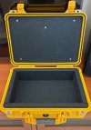
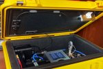
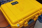
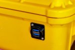
  • DIY noise isolation container made from Pelican 1500 case
03 P1420419.jpg


04 20210414_Noise Isolation Case.jpg05 P1430043a.jpg06 P1430048a.jpg07 P1430046.jpg

Calibrations:​

1. REW Soundcard calibration:
Setup:
RME Babyface Pro FS 3.5mm HP OUT (Left Ch) --> B&K 1704 IN1 > B&K 1704 OUT1 --> RME Babyface Pro FS XLR IN1

RME Babyface Pro FS 3.5mm HP OUT Analog 3(L) & 4(R) volume level: 0 dB
B&K 1704-C-102 gain: 0 dB (x1)
B&K 1704-C-102 filter: Linear
RME Babyface Pro FS XLR Input 1 gain: 6 dB
Calibrated to flat frequency response.

2. REW Microphone calibration:

IEC 60318-4 compliant coupler, E610A SN:20229
Calibrated to GRAS RA0045-S1.

3. REW SPL calibration:

ND9B SPL Calibrator set at 94 dB SPL (1 kHz)
REW SPL Meter reading calibrated to 93.6 dB SPL
Setup Dynamic Range: 135 dB SPL


Notes on SPL calibration:
Based on SPL measurement comparisons with Etymotic ER4XR, the ND9B unit that I use seems to output 94.5 dB SPL instead of exactly 94.0 dB SPL. With 0.9 dB correction factor based on measurement of the IEC 60318-4 Coupler SPL attenuation, the SPL calibration of my setup is set at: 94.5 dB SPL - 0.9 dB = 93.6 dB SPL.

4. Calibrations for Electrical Impedance measurement:
Calibrations as per REW impedance measurement recommendations:
REW Impedance Measurement
  • Open circuit calibration, Short circuit calibration, and Reference resistor calibration (16 ohms).
  • Level / Headroom calibration:
    • 3 ohms load: 33.3 dB Headroom
    • 600 ohms load: 6.2 dB Headroom

Settings & Conditions:​

General setting & conditions for frequency response and distortion measurements:
Ambient noise inside the noise isolation container: < 28 dBA SPL (measured)
Ear Tip: Stock medium size silicone ear tip is the default ear tip for measurement. If for any reason the stock ear tip is not available, other suitable silicone ear tip will be used as the replacement.
Headphone amplifier output impedance: 0.15 ohms (measured)
Audio driver and sample rate: ASIO – 96 kHz
IEC 60268-7 test level for most tests (except THD measurement @ 104 dB SPL): 94 dB SPL @ 500 Hz
Result: RAW (uncompensated)

RME Babyface Pro FS 3.5mm HP OUT Analog 3(L) & 4(R) volume level: 0 dB
(signal level set on REW generator)
B&K 1704-C-102 gain: 0 dB (x1)
B&K 1704-C-102 filter: Linear
RME Babyface Pro FS XLR Input 1 gain: 6 dB


Setting & conditions for Electrical Impedance measurement:
Test setup as per REW article for impedance measurement:
REW Impedance Measurement

Rsense: 75 ohms
Audio driver and sample rate: Java – 96 kHz

Headphone Output:

RME Babyface Pro FS 3.5mm HP OUT Analog 3(L) & 4(R) volume level: 0 dB
Signal level set on REW generator: -18.0 dBFS (approximately: 216 mV)

Soundcard Inputs:
RME Babyface Pro FS TS Input 3(L) & 4(R) gain: 9 dB (Windows driver input level set to 100%)

08A Impedance Setup.jpg


08B 2021-12-29_111400.png


Measurement:​

Frequency Response​

Method: Continuous Sweep
Measurement Frequency Range: 16 Hz - 22 kHz
Observation Frequency Range: 20 Hz - 10 kHz
Level: 94 dB SPL @ 500 Hz
Sweep Length: 1 Million Samples
Repetitions: 4x
Smoothing: 1/48th of an octave smoothing

Left-Right Match​

Range: 20 Hz - 7 kHz
(Data from frequency response measurement result)

Total Harmonic Distortion​

Method: Stepped Frequency Sweep
FFT Length: 128k
Windows: Blackman-Harris 7
Average: 4
Max overlap: 93.75%
Frequency Range: 20 Hz - 20 kHz
Frequency Step (PPO): 6
Lock Frequency to the RTA FFT: enabled
Add Dither: enabled (24 bits)
Level: 94 and 104 dB SPL @ 500 Hz
Observation Frequency Range: 55 Hz – 7.1 kHz (THD through 6th harmonic)
Measurement Points: 43

Intermodulation Distortion (IMD)​

SMPTE & DIN
IMD measured at 94 dB SPL @ 500 Hz

Electrical Impedance​

Method: Continuous Sweep
Measurement Frequency Range: 20 Hz - 20 kHz
Level: -18.0 dBFS (approximately: 0.216 Vrms)
Sweep Length: 1 Million Samples
Repetitions: 1x
Noise Filter: Medium
Observation Frequency Range: 20 Hz - 20 kHz
Resolution: 96 PPO (points per octave)
Smoothing: 1/48th of an octave smoothing
Measurement Points: 957 points

Sensitivity​

30 seconds of Loudness Equivalent (LAeq) of 50mV full range Pink noise playback. The 50mV level is measured using 500Hz tone.
Expressions: ... dBA SPL / 50mV of Pink noise (50mV set at 500Hz)

Metal shell to ground pin connection​

 
Last edited:

Sound Quality​


Tonal Balance​

Earfonia IEM Target Curve - EITC-2021​

As we know frequency response target curve for In-Ear Monitor (IEM) is not a flat line as commonly expected for speakers. This is due to what is called the head-related transfer function (HRTF). There are several target curves for IEM frequency response that are being used in the industry, but none has been considered as a common international standard/consensus for the In-Ear Monitor frequency response target curve. The Harman Target Curve for IEM 2019 is probably one of the most popular among those target curves and the one that is probably the closest to my target curve.

The primary reason for the lack of consensus for the IEM frequency response target curve could probably be the consensus of the methodology of how the target curve should be measured. Besides that, HRTF varies from person to person. Another reason is the fact that frequency response measurement results of an IEM may differ between different measurement equipment. Because of those reasons I have come up with my own target curve that suits my listening preference and is compatible with my measurement equipment. This target curve is subjectively my ‘perceived neutral’ target.

My approach is simple, I look for IEMs with a tonal balance that is close to my perceived neutral. Perceived neutrality is highly dependent on the recording material we use for observation. Besides ‘audiophile recordings’ I also use my own recordings raw tracks for the observation (mostly piano and vocals). The selection process took more than 2 years. Initially, there were around 10 IEMs selected, but in the end, I chose 5 of them. After that, I measured those IEMs and created the average frequency response from the measurements and reconstructed the estimated target curve to create the ‘smooth’ version of the target curve. I’ve made several drafts and finally, I’m quite satisfied with the latest draft that I think is good enough to be my target reference for IEM frequency response analysis. I named it ‘Earfonia IEM Target Curve 2021’ or ‘EITC-2021’ in short.

09 EITC-2021.png


None of the 5 IEMs are perfectly matched to my target, but all have a high degree of naturalness to my ears. Obviously, they don’t sound the same, one may sound a bit more mid centric and other may sound a bit more V shape in tonality. What makes them unique to me are they are within a close range to my target. So, the average frequency response of the 5 IEMs is the base for Earfornia IEM Target Curve.

The 5 selected IEMs are:
1. A prototype IEM given to me by a local IEM brand for testing. I cannot disclose any further detail about it. It just sounds right to my ears, balanced and pretty close to my perceived neutral. Just for referencing, I named it STP.
2. SeeAudio Yume. Perceived tonal balance is pretty neutral to me and at the time of writing, it is among the top 5 IEMs closest to Harman IE Target 2019 in the HypeTheSonics database. Mids may sometimes sound a tad lean but overall, it is a good neutral reference IMHO.
3. IKKO OH1. Mildly V shape tuning. It just sounds right with practically all recordings I played on it. Lively and engaging. One of my all-time favourite IEM.
4. TFZ King Pro. Mildly V shape tuning. Often perceived as neutral with classical, acoustic instrumental, and orchestral works. One of my top favourite IEM for classical recordings. Represent the maximum V shape tuning that for certain recording can still be perceived as neutral.
5. Moondrop KXXS. Neutral with a tad mid centric tonality. The mids of KXXS sounds perfectly neutral to my ears. I prefer to have a tad more sub bass and upper treble presence from KXXS. KXXS is a good IEM to represent my acceptable limit of a slightly mid centric tuning.

I applied a custom weighting for averaging the graphs. I doubled the weighting for STP and SeeAudio Yume as they represent the more balanced tuning among the 5. Then I averaged the 7 frequency response graphs. The following is the (custom weighted) averaged measurement curve from the selected 5 IEMs (Red curve) and the EITC-2021 smoothed reconstructed curve (Blue curve):

10 EITC-2021 - Selected IEMs FR.png


EITC-2021 is more suitable as a target curve for IEMs designed for regular insertion depth (~ 20mm from eardrum / IEC coupler microphone membrane). For the deep insertion (< 16mm from eardrum / IEC coupler microphone membrane) IEMs such as the Etymotic ER series and some micro drivers IEMs the treble dip and resonance peak frequencies will be higher.

EITC-2021 is not meant to be a static target curve, but it is more of an estimated target of a dynamic target. A dynamic target as the value of frequency peaks and dips are not static values but a range of preferred values. For example, the midrange peak shown in the graph is at 2.7 kHz, but it is actually a range from 2.3 kHz - 3.1 kHz. So, a midrange peak measured in that range is considered acceptable and within the range. For the same reason, I prefer to present all frequency response graphs in raw without any compensation. I think there is still a lot to learn about how to meaningfully interpret IEM frequency response graphs, therefore simple frequency response compensation to a static target curve potentially might cause misinterpretation. I will elaborate more on my preferred way of dynamic interpretation of IEM frequency response graphs in the frequency response analysis section.

My observations so far from my own measurement:
● There are IEMs that sound very good to my ears (not necessarily close to perceived neutral) with FR graphs that are not in agreement with the EITC-2021 target curve.
● So far there is no IEM with FR graph that is closely matched to EITC-2021 that sounds unbalanced in the tonality.

For the reasons above, the rating for Tonal Balance will be a combination of objective comparison to EITC-2021 and my personal subjective listening test. EITC-2021 is a work in progress. I might revise it in the future if necessary. It is not a perfect target; therefore, the listening test is still my highest priority in sound quality evaluation. But the target curve is a necessity for objectivity.


Comparison to Harman IE Target Curve - 2019​

I know that I shouldn’t compare The Harman Target Curve for IEM 2019 with my EITC-2021 because of different measurement equipment and methodology. But some (including myself) might be curious about how they compare so here is the comparison:

11 EITC-2021 - Harman Target 2019.png


The preferred bass level is surprisingly very close. Bass is a personal preference, so there won't be any consensus on how much should be the exact bass level for a target. My personal preference for bass is more or less in agreement with the Harman Target. The higher level at around the 60-400 Hz area could probably be due to the different measurement equipment or my personal preference for a slightly fuller sounding midrange. FYI I’m not a fan of a recessed-sounding midrange.

The biggest difference between the 2 target curves is on the treble area around 5 - 10 kHz. We ignore the area above 10 kHz because it is beyond the accuracy range of the IEC 60318-4 Ear Simulator. My guess the difference is due to the different method of formulating the target curve. We can read the measurement methodology of Harman Target Curve from the following document:
PERCEPTION & MEASUREMENT OF HEADPHONE SOUND QUALITY: IS THERE A PREFERRED TARGET RESPONSE?

From what I read the Harman Target Curve for IEM (IE Headphones) seems to be an estimated target curve based on the listeners’ preference and may not be an estimated average response from real IEM measurements. That's why the treble response between 5-10 kHz doesn’t seem to be a realistic target for measurement since it has smoothed out (ignored) the treble dip and the resonance peak that show in most IEMs measurement using the standard IEC 60318-4 Ear Simulator.

The resonance peak frequency depends on the insertion depth of the IEM to the IEC 60318-4 coupler, and it is usually in the range of 8 - 11 kHz due to the λ/2 distance between the IEM and IEC coupler mic membrane. And the treble dip follows right before the resonance peak, usually between 6.5 - 9 kHz, most often at around 7 kHz. I observe that the treble dip is a good indicator of treble sharpness and sibilance, therefore, to ignore it makes the treble part of the Harman Target Curve an unrealistic target for measurement. From my observation, my preferred level of the treble dip is at around the same level as the midrange dip with ±3 dB of tolerance. While on the Harman Target Curve that area shows a much higher level than the midrange dip. Meaning if my observation is correct, if an IEM frequency response at around 7kHz area matches the Harman Target Curve, it will have an unnatural sharp treble that is prone to sibilance. But again, my observation is based on different measurement equipment, so my conclusion here may not be accurate. And that’s also one good reason why I cannot use Harman Target Curve for my IEM measurement (even after my best effort to calibrate my measurement setup to G.R.A.S. RA0045 Ear Simulator, the same model of IEC coupler that was used to measure the Harman Target Curve) because the treble area is proven to be an unrealistic target for my measurement setup.


Frequency Response Analysis​

The objective of analyzing the IEM frequency response graph is to estimate the perceived tonal balance of the IEM. As mentioned earlier EITC-2021 is a dynamic target. There are several observation points on the target curve, and the value of the frequency and level of the observation points are a preferred range of value rather than a static value. The suggested observation points on the target curve are as the following:

12 EITC-2021 1080p.png


13 EITC-2021 - Perceived SQ 1080p.png


Observation Points:

B60
: 60 Hz is at the border between sub-bass and bass area. Although the sub-bass level is sometimes measured higher than the 60 Hz level, our hearing sensitivity for frequency below 60 Hz is lower than for frequency above 60 Hz. Therefore, I think 60 Hz is a good point to observe the overall perceived bass level. Bass level is a personal preference, my preference is B60 (bass level @ 60 Hz) at around 2.5 dB (±3 dB) below the Midrange Peak.

MRP: Measurement Reference Point, 500 Hz at 94 dB SPL. The loudness reference for setting the output level of the headphone output. Although frequency response measurement is less affected by the loudness level, this level is critical for distortion measurement.

Md: I didn’t set any preference for the Midrange Dip frequency, typically midrange lowest dip point can be between 200 - 900 Hz. Midrange Peak and Treble Dip level are measured in reference to the midrange dip level.

Mp: Midrange Peak is one of the most important measurement points. This is the natural ear resonance of the ear canal and eardrum and is responsible for the perceived midrange presence. The very important peak for vocal presentation. From several articles that I read; this primary peak of ear resonance is approximately +17 dB at 2,700 Hertz. My preferred frequency range for Mp is between 2300 - 3100 Hz, with a level around +10 dB ±3 dB above the level of Midrange Dip. I’m not sure why my personal preference for the level of the primary resonance peak is far lower from +17 dB. I found that beyond +13 dB vocal may sound a bit shouty and too in your face kind of presentation.

T1p: Sometimes called the secondary peak, this is the resonance frequency of the concha of the ear. I call it the 1st Treble Peak. T1p is sometimes not shown on some IEM frequency graphs, or less emphasized. I found that T1p is important for perceived clarity, therefore I prefer the T1p to have a certain level of emphasis. My preferred frequency range for T1p is between 4000 - 5000 Hz, with level around 1.5 dB (±3 dB) below the Midrange Peak.

Td: I observed that Treble Dip is a good indicator for treble sharpness or the level of sibilance. Therefore, I call it Sibilance Dip. I don’t have any preference for Td frequency, but it is typically around 7kHz. It gets higher with deeper insertion IEMs. My preferred level for Td is around 0 dB (±3 dB) from the Midrange Dip. So more or less on the same level as the Midrange Dip.

T2p: When the ear canal is closed by an IEM, it acts as a closed tube. And the length of the closed tube is the half lambda for the 1st resonance frequency of the tube. That’s the reason that this 2nd treble peak indicates the insertion depth of the IEM into the IEC coupler because when an IEM is inserted into the IEC coupler it creates a kind of closed tube with the length around the half lambda of the T2p frequency. The deeper the IEM inserted into the coupler, the higher the resonance frequency because the length of the tube is shorter. I don’t use this point as a point for tonal balance observation because the frequency and level are highly influenced by the insertion depth of the IEM into the IEC coupler, therefore it is not a consistent observation point for tonal balance analysis. I use this peak as a measurement point to observe the insertion depth of the IEM, and during measurement, I try to match this resonance peak between the left and the right channels for a more consistent insertion depth between the 2 channels. I usually insert the left channel first into the coupler with a moderate insertion force, until the IEM is inserted properly and won’t fall out by itself from the coupler. After the left channel measurement, then when measuring the right channel, I adjust the insertion depth until the T2p frequency of the right channel matches the T2p frequency of the left channel. This process of matching the T2p of the right channel sometimes takes more than 15 minutes. I use a mounting putty to keep the IEM stable in its place. Otherwise, it is very difficult to keep the insertion depth consistent during measurement. Although T2p frequency varies with insertion depth of the IEM into the coupler, the level could give us some indication of the perceived treble level around this 8-10 kHz area. I cannot set an accurate target level for T2p, but I prefer the T2p level to be around the same level as the T1p. When the T2p shoots up higher than T1p usually we can hear some emphasis on treble sharpness on that 8-10 kHz area.

The following are my steps to analyze the IEM frequency response graph:

1. Midrange dip (Md) normalization. For measurement we normalize the SPL level at the 94 dB SPL at 500 Hz. But for frequency response analysis I propose to normalize the midrange dip to the same level of the target curve midrange dip, which in this case also at 94 dB SPL.

2. Midrange peak (Mp) level calculation. Mp level is calculated in reference to the level of midrange dip (Md):
Mp - Md ≈ 10 dB ±3 dB.

3. B60, T1p, Td, & T2p level calculation. Bass (B60) and the 1st Treble peak levels are to be compared to the Midrange peak and not the midrange dip. This is probably the key difference between my method and the usual way of frequency response analysis. For example, we often see the bass level in reference to the midrange dip, but in my observation, it is more important to see the bass level in reference to the midrange peak and treble peak. The reason is the bass level reading from the midrange dip alone is not very meaningful without the relation to the midrange peak and treble peak. We might see a bass level like 12 dB above the midrange dip and we might think that the IEM will sound warm and bassy. But if the midrange peak and treble peaks let’s say 15 dB above the midrange dip, the IEM will not sound bassy, but it could probably sound a little bright because Mp and T1p are higher than the bass level.
There is no exact target level for T2p but my preference is for the T2p level to be more or less equal to the T1p level.

The calculations in this step base on my preference:
B60 - Mp ≈ -2.5 dB ±3 dB
T1p - Mp ≈ -1.5 dB ±3 dB
Td - Md ≈ 0 dB ±3 dB
T2p ≈ T1p


Perceived Tonal Balance​

The listening test is always the most important part of the IEM review process. Here is where I give the final rating for the overall Tonal Balance. Observation from the target curve observation points doesn’t tell us the whole story. There are other aspects of the Tonal Balance that are best described by words. I will try my best to be consistent with my target curve, but sometimes I have to deviate from it a little bit if my ears tell me otherwise. Below is the tonal balance rating guideline.


Other Sonic Qualities - Liveliness​

Some said it is all in the frequency response measurement results. It is probably true, but other than the tonal balance, sonic qualities such as perceived detail, clarity, transient, attack, dynamic, tonal density, holographic spaciousness, etc. are hard to read from the frequency response graph. Human subjective interpretation of the overall sound quality I think is still essential in any review of audio equipment, especially transducers such as In-Ear Monitors, headphones, and speakers.

The objective for the ‘Other Sonic Quality’ evaluation is to share my subjective perception of the sonic qualities of the IEM that make the IEM sounds livelier and more lifelike. As mentioned earlier, some of those sonic qualities are perceived detail, clarity, transient, attack, dynamic, tonal density, and holographic spaciousness. It is quite subjective until we have a better understanding of how to quantify those qualities on measurement. Some may call it the ‘Technicalities’ aspect of the sound quality but I prefer not to use that term because ‘Technicalities’ may give the impression that it is an aspect that is objectively measurable and quantifiable. Well hopefully in the future it will be measurable and quantifiable, but for now, it is an aspect from the sound quality that can only be subjectively evaluated. My objective for this evaluation is the more lifelike and livelier the better. For the lack of a better word, I just call it ‘Liveliness’. It is an overall impression of liveliness by the sonic qualities mentioned above.

Rating is used to make simple comparisons between ‘The Perceived Liveliness’ quality of one IEM to the other. Rating is done by subjective listening test and comparison to other IEMs. Please be reminded that this rating is only a subjective rough estimation of the ‘Liveliness’ aspect of the sound quality, and the interpretation of ‘Liveliness’ may be different from person to person.

The following is my guideline for the sound quality rating criteria:

14 Earfonia Sound Quality Rating_2.png
 
Last edited:

Engineering Quality​


• Left-Right Match
• THD @ 94 dB SPL and 104 dB SPL
• IMD SMPTE and DIN
• Electrical Impedance
• Sensitivity
• Fit, Comfort, & Build Quality
• Metal shell to ground pin connection

Ratings for the engineering quality are based on my own measurement statistic data. That means the targets are all realistic values and practically achievable. It also factors in the limitation of my current measurement setup. But since most of the time we are limited to checking only one sample, this quality check doesn’t represent the overall manufacturing quality control of the factory.

15 Earfonia Engineering Quality Rating.png


Left-Right Match​

Practically I prefer to see less than 2 dB Left-Right matching and 3 dB is still considered acceptable especially on lower priced IEMs. From my own measurement I’ve seen that target is achievable even on sub $50 IEMs. Range of observation is only from 20Hz to 7kHz as above 7kHz the measurement is less consistent and highly affected by the IEM insertion depth to the IEC coupler.

THD @ 94 dB SPL and 104 dB SPL​

Harmonic distortion measurement is categorized under engineering quality check because it is not meant to be used for sound quality evaluation.

Harmonic distortion in relation to the perceived audible sound quality is a very big and complex topic to discuss and beyond the scope of this writing. We are not listening to a pure tone and harmonics are part of the music. Therefore, in most cases harmonic distortions just blend in into the music, hiding in plain sight and it is almost impossible to audibly recognize them and distinguish them apart from the music signal.

Although harmonic distortion doesn't seem to have enough significance for sound quality evaluation, one thing that I think we all agree, the lower the harmonic distortion, the better. Low harmonic distortion is a sign of good engineering quality that in my opinion deserves recognition.

Distortion measurement in my review and measurement serves the following:
1. Recognition of good engineering on very low distortion IEMs.
2. Left-Right distortion profile match. Left and Right channels are expected to have similar profile and level of distortion. If the THD curve of one channel is significantly different from the other channel it could be an indicator that one channel might have a problem or manufacturing issue. In this case distortion measurement functions as quality check.

Example of a pair of IEMs with a similar frequency response between left and right channel but a different profile of THD curve between the channels:

16 Tin HiFi T1 Plus FR.png


17 Tin HiFi T1 Plus - Left Channel THD 94 dBSPL.png


18 Tin HiFi T1 Plus - Right Channel THD 94 dBSPL.png


The observation frequency range for distortion measurement is between 55 Hz – 7.1 kHz (THD through 6th harmonic). That is because it is very difficult to isolate very low-frequency noise (below 40 Hz) from the environment and it often affects the distortion measurement on the sub-bass area. Therefore, I consider that distortion measurement on the sub-bass area is not accurate. Since human hearing is not sensitive to harmonic distortion around the sub-bass area, it is best to just ignore it. I want to start the observation at 60 Hz, but the nearest available sampling measurement point is at 55 Hz, so I chose to start the observation point at 55 Hz. The resonance peak area is also considered as another area with low accuracy for distortion measurement. So, the end of the observation area is at 7.1 kHz just before the >8 kHz resonance peak area. Since we do measurement with a 96 kHz sampling rate, we still get up to the 6th harmonic at the 7.1 kHz measurement point. A total of 43 measurement points from 55 Hz to 7.1 kHz. Better than the common IEM specification that only states THD at 1 measurement point at 1 kHz.

Distortion measurement requires low ambient noise conditions during measurement for higher accuracy. That’s the reason to place all the measurement setup inside the Pelican 1500 case with the added 1-inch dense rubber mat inside the case. The case functions as a noise isolation container to reduce the ambient noise. Below is the measurement of the ambient noise with the Pelican case lid opened (Red graph) and closed (Black graph) using MiniDSP UMIK-2 measurement microphone. The noise isolation container started to become effective from around 55Hz and above. And measured ambient noise inside the container is always below 28 dBA SPL.

19 Ambient Noise - Pelican Case CLOSED 10.png


IMD SMPTE and DIN​

IMD measurement serves similar objectives as the THD measurement described above. I hope one day we could find the correlation between IMD measurement and certain aspects of sound quality. For that reason, I included the IMD distortion measurement. I read in an article that in section 8.7.3 of IEC 60268-7 it is suggested to use frequencies of 70 Hz and 600 Hz—with an amplitude ratio of 4:1 for headphone IMD measurement. But that frequency combination of IMD measurement is not available in REW tone generator. And I’m not sure the REW RTA will accurately measure the IMD distortion when I use the custom multitone generator. Therefore, I just use the common SMPTE and DIN IMD measurements.

Electrical Impedance​

Unlike speaker impedance that usually categorized into a certain ‘nominal’ value like 4Ω, 8Ω, and 16Ω for power amplifier matching, that concept of certain nominal impedance is not very relevant for IEM. Power requirement is generally not an issue with IEM as it usually requires less than a milliwatt to achieve the desired loudness while most headphone amplifiers these days usually have output power higher than 30mW at 32-ohm. What might cause an issue is the impedance fluctuation of the IEM when paired with a headphone amplifier with high output impedance. A common issue when using professional audio equipment as it is quite common that the headphone output on pro audio equipment has high (sometimes very high) output impedance.

Once I recommended a pair of IEMs to a friend. In my setup the IEM sounds very good. He bought it and then complained to me that it doesn’t sound very good and sounded too bright in his setup. After some investigation I found the following:
• The IEM impedance curve started at 2.5 ohms at 20 Hz, then ramping up to 19.3 ohms at 20 kHz. Around 10.8 ohms at 10 kHz. So, from 20 Hz to 10 kHz the impedance increased more than 4x.
• I use RME Babyface Pro FS for playback with headphone output impedance around 0.15 ohms, and other DACs that also have very low headphone output impedance. So, the IEM’s tonality won't be altered by the wild fluctuations of the IEM’s impedance.
• My friend used Steinberg audio interface with headphone output impedance around 90 ohms. This high output impedance of the headphone amplifier totally ruined the tonality of the IEM and makes it a lot brighter than what it is supposed to be. Finally, he swapped the audio interface to MOTU M2 and confirmed that the IEM sounded a lot better from MOTU M2 that has headphone output impedance around 0.06 ohms.

For those who are not familiar with the effect of high output impedance of a headphone amplifier, Julian Krause explained here:

The problem with high headphone output impedance happens to me quite often. I also use Steinberg and other audio interfaces for recording, and other pro audio equipment like mixing consoles. They all have various values of headphone output impedance from low to high. Not only Pro Audio equipment, sometimes laptop and mobile phone headphone output may have high output impedance too. For example, my Lenovo T14 office laptop headphone socket has an output impedance of around 40 ohms. What is important from IEM impedance is not the nominal / rated value, but the impedance linearity. That’s the reason I rate the impedance linearity in my measurement because it is important especially for people like me that use headphone outputs from various equipment. Rated impedance alone is not very useful, we need the impedance curve and some important statistic values of the impedance curve to use the IEM properly. Impedance linearity is indicated by the value of the ‘Coefficient of Variation’ (CV) which is the ratio of the standard deviation to the average value of the impedance across the audio band. The lower the CV value the better. CV=0 means the impedance curve is ruler flat.

As for the rated value of the IEM impedance, I haven’t found any standard that defines the calculation of IEM rated impedance. For a speaker, the IEC60268-2 only limits the decrease of the impedance so that the speaker minimum impedance at any frequency doesn’t fall below 80% of the nominal / rated impedance as the speaker impedance curve is generally not a flat line. IEM impedance curve on the other hand doesn’t follow any specific curve characteristic. Many single dynamic driver IEMs have ruler flat impedance while some IEMs with BA drivers may have a very high impedance swing across the frequency range. To calculate the nominal / rated impedance for IEM I suggest the following approach:

Compare the value between ‘Minimum impedance / 0.8’ and the ‘Average Impedance’, then take the lower value as the value for the ‘Rated Impedance’.

The following is a measurement comparison of a few fix resistors, comparing the resistors’ DC resistance measured using a multimeter and the impedance using the impedance measurement setup above. We can safely say that the accuracy of the setup is within 0.1 Ω for measurement between 0 – 600 Ω.

Resistor Nominal Value (Ω)​
DC resistance on Multimeter (Ω)​
Impedance at 1kHz (Ω)​
3​
3.04​
3.00​
16​
16.05​
16.00​
600​
599.7​
599.1​

Sensitivity​

I have the Creative SXFI® AMP, a small USB-C dongle DAC. When I pair it with my 1964 EARS V3 IEM the volume level is usually maxed at 5/100 before it gets too loud. Usually, I only get 3 steps of volume to play around with or probably 4 steps with softer recordings. Another problem with IEM with super high sensitivity like the 1964 EARS V3 is that it is practically a noise floor magnifier. It lets me easily hear the hissing noise floor from the headphone amplifier. I measured the listening level with a 1kHz tone, it is around 8mV – 16mV (Volume level 2-4). Don’t expect to experience 96 dB of CD dynamic range with this high sensitivity IEM, consider it lucky if we get 80 dB SNR at that output level. The point is IEM sensitivity is an important parameter to be considered before getting an IEM. And it would be great if the IEM sensitivity number is directly related to the headphone output at listening volume level for most IEMs, which is around 50mV. So, we can easily see the correlation of loudness to the average volume level.

Some use 1mW and other use 100mV at 1khz as the reference point. 2 IEMs with vastly different frequency response curves might have a similar level of sensitivity at 1kHz. But when we play them at the same volume level the overall perceived loudness could be noticeably different. Using 1kHz reference point to estimate the IEM sensitivity is inaccurate.

I think the better way to measure IEM sensitivity is to use a broadband signal like pink noise and measure the SPL of the output. The article below titled ‘IEC-60268-7 Headphone Test Sequences’ from ‘Listen, Inc.’ describes the sensitivity measurement using pink noise, but it seems a bit complicated and requires pink noise, 20Hz-20kHz, shaped according to IEC 60268-1.

IEC-60268-7 Headphone Test Sequences

Therefore, for the practical reason I suggest the following approach for IEM sensitivity measurement:
1. 50mV output at 500Hz. Set the tone generator to generate 50mV output at 500Hz. Measure the headphone output using True RMS digital multimeter. I suggest using a 16ohms dummy load connected to the headphone output when setting the volume level to get the 50mV output. On my setup the generator level is -30.65 dBFS for 50mV at 500Hz.
2. Loudness measurement with Pink Noise. Disconnect the dummy load and connect the IEM under test. Playback a full band Pink noise at the same volume level set in step 1. Measure the IEM output loudness on the REW SPL meter. Set A-weighting on the SPL meter, then measure the loudness equivalent (LAeq) for about 30 secs to get a stable average reading. This LAeq SPL reading is to be used as the IEM sensitivity.

The IEM sensitivity will be expressed as the following: ... dBA SPL / 50mV of Pink noise (50mV set at 500Hz).
It may not be the most accurate way to express it, I’m not an expert in this. Any suggestion for a better way to express it is welcomed.

20 2022-01-02_012317.png


Fit, Comfort, & Build Quality​

Although very subjective it is still a useful observation. Certain IEM shapes and sizes can be problematic to most people, while others might provide a good fit and comfort for most. Generally, I very seldom have fit and comfort issues from most IEMs that I’ve tried. And I’ve tried quite a lot for the last decade. I can say more than 95% of all the IEMs that I tried fit my ears quite well. Some of them may not be very comfortable over a long listening session, but I generally don’t have issues with IEM ergonomics.

Build quality observation look into the potential problem in the utilization, and less from the aesthetic point of view.

Metal Shell to Ground Pin Connection​

Sometimes I get an electric byte when wearing IEM with a metal shell when connected to my old laptop with the charger on. Not a pleasant experience at all and quite irritating. That’s the reason for me to check the ground pin connection with the metal shell.
 
Last edited:

Standards & References​


The following standards are for references only. My setup and methodology may not be fully complied with those standards.

Standards:​


IEC 60268-7

IEC 60318-4

IEC TS 62886:2016

Preview document page 7:

“The occluded-ear simulator as described in IEC 60318-4 simulates the average human external ear up to 8 kHz, and can be used as a test coupler up to 16 kHz. The occluded ear-simulator is designed for a specific insertion depth of the earmould, which is associated with a half-wavelength λ/2 resonance at about 13,5 kHz. This half-wavelength resonance degrades the reproducibility of measurement results in that frequency range and harmonic distortion measurements made at corresponding multiples of the resonance frequency. Also, this resonance represents a complex load to the hearing aid transducer, which makes it more difficult to differentiate between transducer and load related effects.”


References:​


HRTF

Ear Resonance

PERCEPTION & MEASUREMENT OF HEADPHONE SOUND QUALITY: IS THERE A PREFERRED TARGET RESPONSE?

Headphone Testing

IEC-60268-7 Headphone Test Sequences

Speaker Electrical Impedance:


Measurement Results (Examples)​


Frequency Response Measurement Comparisons Between E610A-SN20229 Coupler and GRAS RA0045-S1 Coupler​

All measurements were done at 94 dB SPL at 500Hz. Left and Right channels graphs are separated by 5 dB after measurement for easier observations. Left channel on the top and Right channel at the bottom. GRAS RA0045 graphs in RED and E610A clone coupler graphs in BLUE. The graphs show the calibration of my E610A clone coupler to GRAS RA0045.

Etymotic ER2SE:
Etymotic ER2SE.png


BLON BL-05:
BLON BL-05.png


Sony MH755:
Sony MH755.png


Frequency Response Measurement of Etymotic ER4XR, ER2XR, ER2SE using E610A coupler in comparison to EITC-2021​

EITC-2021 - Ety ER4XR - Ety ER2XR - Ety ER2SE.png
 
Last edited:
Excited to see the outcome of measurements on this project. Good luck.
 
Anyone with Etymotic ER2XR and would like to try my EITC-2021 target curve, attached is the equalizer profile for ER2XR to match the EITC-2021 frequency response. The file is to be used/loaded to Equalizer APO. Please apply around -3.0 dB gain compensation to avoid clipping. Or just create a new text file with the following lines:

Filter Settings file

Room EQ V5.20.4
Dated: 5 Jan, 2022 12:13:08 AM

Notes:Etymotic ER2XR v1.0

Equaliser: Generic
A over B
Filter 1: ON LS Fc 37.00 Hz Gain -0.50 dB
Filter 2: ON LS Fc 135.0 Hz Gain 2.00 dB
Filter 3: ON PK Fc 445.0 Hz Gain -0.90 dB Q 0.850
Filter 4: ON PK Fc 880.0 Hz Gain 0.30 dB Q 2.000
Filter 5: ON PK Fc 1315 Hz Gain -1.70 dB Q 1.150
Filter 6: ON PK Fc 2423 Hz Gain -1.70 dB Q 1.850
Filter 7: ON PK Fc 4585 Hz Gain 2.70 dB Q 3.150
Filter 8: ON HS Fc 8000 Hz Gain 1.50 dB

Etymotic ER2XR - EQ APO - 2022-01-05.png
 

Attachments

  • Etymotic ER2XR v1.0.txt.zip
    490 bytes · Views: 111
Excited to see the outcome of measurements on this project. Good luck.

This is the first review using this methodology:
 
Very impressive! Did you have a chance to check the InEar Prophile 8? I have seen other measurements where it seemed to match your target curve quite well.
 
Very impressive! Did you have a chance to check the InEar Prophile 8? I have seen other measurements where it seemed to match your target curve quite well.
Thanks! I tried Prophile 8 a few years ago, like it a lot. Sounds balanced to my ears, just a tad warm. But I didn't have the budget to get a pair :)

It has a few tuning, I forget all the tuning variations but to my ears at that time, the default neutral tuning sounds best.

I didn't have measurement equipment at that time, so I haven't got the chance to measure it.
 
Thanks. Options are a slight Bass and Treble boost (both on for me). Found the old measurements:


Comparison to Harman IE Target Curve - 2019​

I know that I shouldn’t compare The Harman Target Curve for IEM 2019 with my EITC-2021 because of different measurement equipment and methodology. But some (including myself) might be curious about how they compare so here is the comparison:

View attachment 176225
Your target has some directional similarity with the USound Target when referenced to Harman-IE. I think it's one more data point telling that Harman IE target has room for improvement.
 

Attachments

  • 68747470733a2f2f692e696d6775722e636f6d2f6b4759424f65762e706e67.png
    68747470733a2f2f692e696d6775722e636f6d2f6b4759424f65762e706e67.png
    129.3 KB · Views: 137
Is it possible? It will vary a lot due to insertion depth effects, I can understand why it's smoothed over.
Like that I have explained above, the treble dip (Td) around 7kHz and the resonance peak (T2p) are very useful to estimate treble sharpness and sibilance. Insertion depth will affect the frequency, but the amplitudes of Td and T2p are still useful info and quite reliable in predicting treble sharpness. The dip and the peak are inherent characteristic of the IEC 60318-4 coupler that shouldn't be smoothed out.

kHTDWiQ.png
 
quite reliable in predicting treble sharpness
Under what conditions? This range will vary quite heavily based on insertion depth. Each user is at the mercy of their individual anatomy and tip size so how do you control for that?
 
Under what conditions? This range will vary quite heavily based on insertion depth. Each user is at the mercy of their individual anatomy and tip size so how do you control for that?

That's true, not for all type of IEMs. My target is for regular insertion IEM, which is probably the majority of the IEMs, and not for deep insertion IEMs like the Etymotics. Under the condition: using the medium size ear tip (~12mm diameter), with resonance peak (T2p on my target) at around 8-9kHz. And it is also true that it might not predict everyone HRTF profile. But for myself, using my measurement setup, so far it is quite predictable. Not 100%, but like around 75% accurate. For example when the sibilance dip (Td) is measured more than 3 dB above the midrange dip (Md) the treble will start to sound sharp and prone to sibilance.
 
Why are you not trying to equalize T2P peak? this peak is only existed when using IEM.
 
Why are you not trying to equalize T2P peak? this peak is only existed when using IEM.

Practically not always possible to match the T2p frequency for every IEM. Not all IEMs designed to have similar insertion depth, or distance from the driver / nozzle to the IEC coupler microphone membrane that resulting the T2p resonance frequency. I tried to do similar insertion depth with the medium size ear tip till the ear tip edge is around 1.0 - 1.5 mm above the edge of the coupler's nozzle. But even stock ear tips are varies. Not all the stock medium ear tip have exactly the same diameter. So I try to achieve similar insertion depth for every IEM but there will differences due to IEM design and ear tip design. For example, IEM with large nozzle diameter will naturally less deep than the IEM with smaller nozzle diameter. That's also the reason I don't put T2p in my frequency response analysis calculation due to the inconsistency caused by the insertion depth. I only go up to Td in my calculation. But in general, my preference for T2p is to be more or less then same level as T1p. Just as preference.

Example of the frequency responses analysis calculation is in any of my review, for example this review:
 
Back
Top Bottom