Yes, but not for IMDThey are there for the 1KHz .

-
WANTED: Happy members who like to discuss audio and other topics related to our interest. Desire to learn and share knowledge of science required. There are many reviews of audio hardware and expert members to help answer your questions. Click here to have your audio equipment measured for free!
- Forums
- Audio, Audio, Audio!
- DACs, Streamers, Servers, Players, Audio Interface
- Audio Interfaces (ADC & DAC)
You are using an out of date browser. It may not display this or other websites correctly.
You should upgrade or use an alternative browser.
You should upgrade or use an alternative browser.
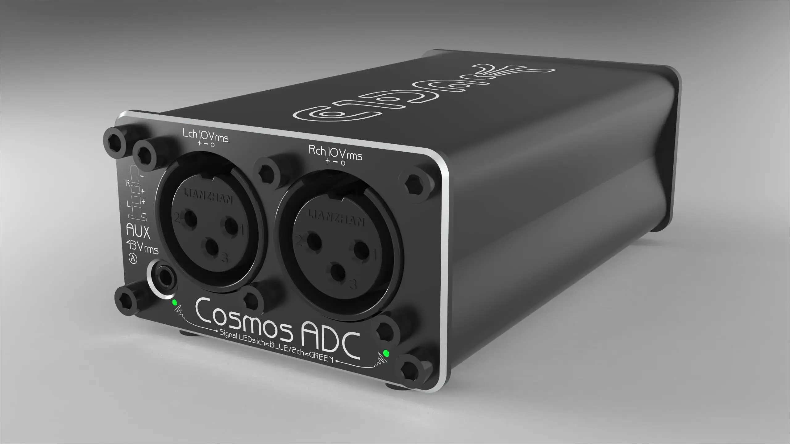
E1DA Cosmos ADC
- Thread starter mansr
- Start date
Yes, but not for IMD
I've not found the REW display of distortions for anything but single tone to be all that useful.
- Thread Starter
- #63
Yes, a simple line driver connected to the LRCK pin would do it. You'd need to check the specs of the receiving equipment for the expected signal level.There's another solution I thought about as I can sync from SPDIF/AES/ADAT or... Word.
The LRCK pin is supposed to output the Word clock (it's the same), but how to get that out ? just linking this LRCK pin and Ground pin to a BNC connector, with maybe something to amplify and regulate the signal ?
The WM8805 chip on that board needs this signal in order to operate. As can be seen in the photos, it is wired to the input connector (via a buffer). The MCLK signal must be supplied externally, or the chip won't do anything at all. It's not part of the I2S spec, but it is still needed by this device. The description says as much too, though it's strangely worded (poor translation).What I don't understand is why the above board would absolutely need the MCLK signal.
Grooved
Addicted to Fun and Learning
- Joined
- Feb 26, 2021
- Messages
- 679
- Likes
- 441
Thanks @mansr !Yes, a simple line driver connected to the LRCK pin would do it. You'd need to check the specs of the receiving equipment for the expected signal level.
The WM8805 chip on that board needs this signal in order to operate. As can be seen in the photos, it is wired to the input connector (via a buffer). The MCLK signal must be supplied externally, or the chip won't do anything at all. It's not part of the I2S spec, but it is still needed by this device. The description says as much too, though it's strangely worded (poor translation).
That's right that I was not sure of the text, but after checking the board, it matches what you said
")
So the easiest way to get a sync seems to build a BNC Word clock output, and still use the Cosmos ADC as recorder via USB. It leads to use two devices with the computer softwares, less easy than what @HiZ want to do if I'm not wrong : sending the digital audio signal to a digital input of only one interface used by the computer (getting Cosmos A-D conversion, but routing it with the same interface doing the D-A)
He may confirm if I'm right
At this moment, after matching the levels, I tried to do a loopback test and check it with @pkane DeltaWave, and the result was not so great, but it's certainly because of the missing sync. Will check further later
Last edited:
Grade 0..
 www.aliexpress.com
139.0US $ |E1DA Cosmos ADC Hi Precision Analog To Digital Converter For Audio Testing Bundle 1=Grade C Bundle 2=Grade B Bundle 3 =Grade A|Digital-to-Analog Converter| - AliExpress
Smarter Shopping, Better Living! Aliexpress.com
HiZ
Member
- Joined
- Apr 26, 2021
- Messages
- 37
- Likes
- 8
That's amazing....Grade 0..
139.0US $ |E1DA Cosmos ADC Hi Precision Analog To Digital Converter For Audio Testing Bundle 1=Grade C Bundle 2=Grade B Bundle 3 =Grade A|Digital-to-Analog Converter| - AliExpress
Smarter Shopping, Better Living! Aliexpress.com
Grooved
Addicted to Fun and Learning
- Joined
- Feb 26, 2021
- Messages
- 679
- Likes
- 441
Hi @mansr ,You'll need to connect those signals to an AES/EBU transmitter such as Texas Instruments DIT4192 or Cirrus CS8406. Both of these require a master clock at 128 or 256 times Fs. This can be generated from the word clock using a clock multiplier, e.g. the Cirrus CS2300-03. You'll also need power supply, output transformer, and some passive components. Maybe there's a ready-made board available somewhere.
do you think that this board would work to generate to MCLK , then sending the 4 signal to another board converting I2S (with MCLK this time) to SPDIF/AES ?
Chipset: CS8421Input Sampling Rate: Up to 192kHz (16 / 32Bit)Constant Output Sampling Rate: 211kHzPower Supply: 5V DC
EDIT : just found one with a 24.576 chip :
aliexpress.com/item/33035364226.html
or this one :
Last edited:
- Thread Starter
- #68
Those boards resample the input to a fixed output rate. That's not what you want.Hi @mansr ,
do you think that this board would work to generate to MCLK , then sending the 4 signal to another board converting I2S (with MCLK this time) to SPDIF/AES ?
View attachment 160699
The point that I'm not sure how to handle it is the constant output of 211kHz :
Chipset: CS8421Input Sampling Rate: Up to 192kHz (16 / 32Bit)Constant Output Sampling Rate: 211kHzPower Supply: 5V DCI suppose that it's due to the 27MHz chip, so would it possible to replace it with a 24.576 one ?
EDIT : just found one with a 24.576 chip :
aliexpress.com/item/33035364226.html
View attachment 160700
or this one :
View attachment 160701
Grooved
Addicted to Fun and Learning
- Joined
- Feb 26, 2021
- Messages
- 679
- Likes
- 441
Right, just realized that some minutes ago, even if it should work if using only 192kHz on the Cosmos ADC, shouldn't it ?Those boards resample the input to a fixed output rate. That's not what you want.
- Thread Starter
- #70
It would work, but the quality of that ASRC chip probably isn't great.Right, just realized that some minutes ago, even if it should work if using only 192kHz on the Cosmos ADC, shouldn't it ?
Grooved
Addicted to Fun and Learning
- Joined
- Feb 26, 2021
- Messages
- 679
- Likes
- 441
Certainly, I thought at first there was a way to run it as slave and bypassing the conversion. I only found in the CS8421 data sheet that it can run as slave, and even bypassing the conversion but I didn't find if it still output the MCLK in this case.It would work, but the quality of that ASRC chip probably isn't great.
Anyway, the CS4821 may be able to do that but this board is not designed like that, it would require to build one from the scratch.
Last edited:
Weeb Labs
Addicted to Fun and Learning
Either the Twisted Pear Metronome or my own Constellation board (much cheaper but unavailable to order until next week) would work well. The reference clock output on my board (and possibly the Metronome) is active regardless of IO mode, unless the RCLK switch is in the off position.Hi @mansr ,
do you think that this board would work to generate to MCLK , then sending the 4 signal to another board converting I2S (with MCLK this time) to SPDIF/AES ?
View attachment 160699
The point that I'm not sure how to handle it is the constant output of 211kHz :
Chipset: CS8421Input Sampling Rate: Up to 192kHz (16 / 32Bit)Constant Output Sampling Rate: 211kHzPower Supply: 5V DCI suppose that it's due to the 27MHz chip, so would it possible to replace it with a 24.576 one ?
EDIT : just found one with a 24.576 chip :
aliexpress.com/item/33035364226.html
View attachment 160700
or this one :
View attachment 160701
- Thread Starter
- #73
Those also use an ASRC.Either the Twisted Pear Metronome or my own Constellation board (much cheaper but unavailable to order until next week) would work well. The reference clock output on my board (and possibly the Metronome) is active unless the RCLK switch is in the off position.
Weeb Labs
Addicted to Fun and Learning
They do. The SRC4192 exhibits a SINAD of 140dB, which is perfectly adequate for any purpose.Those also use an ASRC.
Last edited:
- Thread Starter
- #75
There's also the jitter aspect which that figure doesn't take into account.They do. The SRC4192 exhibits a SINAD of 140dB, which is perfectly adequate for any purpose.
Weeb Labs
Addicted to Fun and Learning
The sum of all uncorrelated jitter is represented by the dynamic range and by extension SINAD/THD+N. Correlated jitter is a somewhat more complex matter but that's going to be largely dependent upon the clock source and not the ASRC.There's also the jitter aspect which that figure doesn't take into account.
- Thread Starter
- #77
Skirting caused by random jitter is typically included in the fundamental when calculating THD+N while distinct spurs count as noise.The sum of all uncorrelated jitter is represented by the dynamic range and by extension SINAD/THD+N. Correlated jitter is a somewhat more complex matter but that's going to be largely dependent upon the clock source and not the ASRC.
Yes, but not for IMD
Here you go, but I don't think that REW is measuring distortions properly for multiple tones:


- Joined
- May 15, 2019
- Messages
- 872
- Likes
- 3,614
For multiple tones you need a measurement function that removes all stimulus tones from the FFT result. The remaning rest is Total Distortion plus Noise, TD+N (not THD+N). Not sure REW supports this at all. AP does.
 www.ap.com
Technical Library
For multiple tones you need a measurement function that removes all stimulus tones from the FFT result. The remaning rest is Total Distortion plus Noise, TD+N (not THD+N). Not sure REW supports this at all. AP does.
I have an app that does that, also (a bit cheaper than an AP
). Some examples I posted a while back:https://www.audiosciencereview.com/...ds/multi-tone-audio-testing.12865/post-382712
At some point, I'll use my own software, but REW is just so much more convenient
Last edited:
Similar threads
- Replies
- 4
- Views
- 827
- Replies
- 26
- Views
- 2K
- Replies
- 3
- Views
- 1K
- Replies
- 58
- Views
- 5K
- Poll
- Replies
- 75
- Views
- 14K