• WANTED: Happy members who like to discuss audio and other topics related to our interest. Desire to learn and share knowledge of science required. There are many reviews of audio hardware and expert members to help answer your questions. Click here to have your audio equipment measured for free!

Does Ethan's Null Tester Prove His Claim?

Is Ethan correct?

  • Yes

  • No

  • I mean his circuit. No his claim on cables.


Results are only viewable after voting.

chris0202

Member
Joined
Aug 7, 2019
Messages
46
Likes
6
Ethan's video on null tester is interesting.

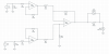
I did a Spice sim using the null control he showed in his video and audioexpress writing, the circled part of is his actual circuit.


actual circuit.PNG


Spice shows that, I can input -1.005V on bottom channel, and 1V on top and still trim down to 4uV versus 1V input, which is a -107 dB loss against input. (Yes, i can get it lower with more time.) And you should check the voltage across R22 (which is what he called null control in his writing), which are -3.4mV and 358 uV.

null control_sim.PNG


That is: null control itself can eliminate a huge voltage difference. (which can be higher but I didn't test). I didn't backward calculate his gain since I don't see actual circuit. Assuming he had reversed phase balanced with non-reversed phase, volt difference should be much smaller than 0.005V against 1V input That's definitely audible since 0.005V is -43 dBu before 80dB gain. This mean Null control can artificially hide audible difference from his two inputs.

Therefore I think the circuit he showed is fundamentally flawed and failed in proving his claim.

So what happened here:

1) He put the null control in the wrong place. He is looking at how well he trimmed the 2 signals, not comparing 2 trimming-matched signals.

2) He never showed the resolution of his test, which is how much difference this tester can ignore.

Any questions?

3) He should simply use a differential circuit as attachment shows. I put a modification up using a differential amp. This circuit can show 100uV difference in input 1/2 correctly. If difference is too small, like 100nV, it will introduce 6nV error and needs some tweak. But 100nV is -140dBv vs 1V input, and it went beyond what opa1612 can do.

4) You might ask, what about sinewave? It doesn't matter, I can get -124dB noise with 1kHz, 5kHz, 10kHz, and 20kHz with sinewave. This sim has no phase issue. So it is only going to be more accurate than what hardware is capable of.

5) This is changes I proposed to make.

****6) "Change only one thing at a time". Read 5) for suggestion D and E for my advice.

7) If we are worried about heat, turn things on until noise settled before doing the demo.

8) Some mentioned this is not his real circuit. I made an update on it as better as I can do. See THIS. It doesn't change my conclusion.

In my sim, Ethan's null tester (the circuit he showed in video) can ignore a -46dBv loss against 1.005V input, which is way louder than minimum audible difference. I believe it can tolerate much larger difference.
 

Attachments

  • differential.PNG
    differential.PNG
    78.4 KB · Views: 133
Last edited:

Wombat

Master Contributor
Joined
Nov 5, 2017
Messages
6,722
Likes
6,463
Location
Australia
Ethan's video on null tester is interesting. I did a Spice sim using the circuit he showed in his video, the circled part of it.

View attachment 47282

Spice shows that, I can input 1.005V on upper channel, and 1V on bottom and still trim down to -100dBv versus 1V input .

View attachment 47293

So what happened here:

1) He put the trimmer in the wrong place. He is looking at how well he trimmed the 2 signals, not comparing 2 trimming-matched signals.
2) He never showed the resolution of his test, which is how much difference this tester can ignore.

In my sim, this stuff can ignore a -46dBv loss against 1V input, which is way louder than minimum audible difference. I believe it can tolerate much higher difference.

Any questions?


Yes. Can this to-and-fro end now? It has become like a needle in a run-out groove or a last man standing thing.
 

solderdude

Grand Contributor
Joined
Jul 21, 2018
Messages
15,997
Likes
36,204
Location
The Neitherlands
A: did you include the tolerances of the resistors in the simulation.
B: @scott wurcer will appreciate you used the AD797 in your simulation
C: why is the null pot in the wrong place ?
D: Yes, he could have used another circuit as well. It's a design choice.
E: why did you choose to have input 1 have 1V and the other have a 0.5% higher signal ?
F: why did you use whole resistance numbers (87 and 113) for the simulation of the null as that does not exactly compensate for the applied 0.5% difference, not realizing the 5.1k in practice also has some tolerance and the pot can be set between 87/113 ?
G: Why do you want the circuit to 'fail' ?
H: Even if the circuit were capable of 'merely' -100dB then what did that have to do with the Sansa's equivalent resolution and noise ?
I: Would even -100dB null, you would still hear something opposite the noise, and yet the music nulled out so was well below the noise floor.

The circuit is intended to null cables (which as we all know are transparent, do not add distortion nor attenuate the audible band which is what is shown here. For this the small nulling range is good enough. One can change the 22 Ohm resistor (not shown in your sim) to increase the range for testing amplifiers etc to get more range to null but requires more fine tune opportunities or use it and adjust gain on the input with a potmeter.

It's a good thing you do not have to say any more though.
And yes... Ethan is correct and I know because I did the same experiment, ust not with a $600.- cable but less expensive and a cheap one and was able to get the exact same result. A bit more noise as I used different opamps 30 years ago.

perhaps go troll somewhere else.
 

JohnYang1997

Master Contributor
Technical Expert
Audio Company
Joined
Dec 28, 2018
Messages
7,175
Likes
18,296
Location
China
I personally genuinely don't like him. There are so many better ways for better results.
 

solderdude

Grand Contributor
Joined
Jul 21, 2018
Messages
15,997
Likes
36,204
Location
The Neitherlands
A: This is minimum noise you can get.

What's your answer got to do with my question ?

B: That's just a name of OA. You can pick a prestored unit so you don't have to alter gain each time you add one. Irrelevant here.

You don't get it. Scott W. will.
And by the way you are saying that the AD797 is similar to the actual used opamp. hmmmm

C: See 1) in original post. If you want to account for voltage loss across cable. You should put a trim after cable, before sending signal into comparator. Otherwise you are altering the output of the comparator.

That's where the pot comes in. It compensates for all amplitude differences due to Ohmic losses + tolerances of the used components. You have to manually null all level differences out. You cannot null the added noise from the input buffers/phase shifter obviously. That's what remains after one adjusted the nulling pot.

D: That's not what he showed. If he used another circuit, his video is still incorrect.

What is incorrect about the video ?

E: Random number. If you prefer 500mV, it is fine. Volt meter reading changed to -5.150uV from 3.960uV with R18=99.9.

I suggest you BUILD the actual circuit and then show the actual values using something like an AP. Then you will see the shortcoming of the simulation.

F: I can go down to 103.41250 ohm and more precise number. But for now, Whole number works fine for -100dB loss. And you cannot really buy these crazy accurarte R anyway. Ethan also won't be able to get it that precisely either.

The nulling range is approx. +/- 0.2% of the input voltage (-54dB of the input voltage) over the trimmer range. you are claiming a potmeter cannot be adjusted quite exactly in the electrical middle ?
The circuit can null perfectly when the input voltage is 1.002V and 1.000V. So yes it cannot null 1.005V to 1V. To null 1.005V you need to remove R14.
It means your randomly chosen 5mV difference is too much difference. It must be less than 2mV difference. It is determined in the design.

G: Interesting. I am just trying to prove his circuit is not working as intended. If you want a working circuit, below is my improved version of it. A differential circuit (aka voltage subtractor), that only output 6nV when input are identical. If you increase difference in input to 5mV, it can show 5mV correctly. It's possible to make gain higher on the differential amp by changing ratio of R19/R20.

You see the device I built 30 years ago ?

dist analyzer.JPG


It actually uses that circuit.

It obtained similar (actually more noisy) results compared to Ethans device.


H: Sansa's noise figure is factored into the input if you want to do further calculation.

WHY ? its noise figure is completely irrelevant. Why insisting it is. The noise from it (or rather the distortion products + noise) are common for both paths and will null. Why do you insist this is not the case ?

I: By NwAvguy, -66dBv loss against peak is minimum audible difference. In this example, I showed that a -46dBv loss in input can be hidden up by the null tester. That means, at least this unit won't output a -46dBv difference passed down by the cables.

You showed nothing.
Ethan showed something and made a video about it which you consider a hoax or 'fake news' because you want cables to sound different or Ethan to be wrong.
 
Last edited:

KSTR

Major Contributor
Joined
Sep 6, 2018
Messages
2,730
Likes
6,100
Location
Berlin, Germany
The only thing that is somewhat questionable is the use of different noise gains for the buffer (1x) vs the inverter (2x) after the input buffers. Bandwidth and distortion are not minutely identical, as are some other resulting parameters like output impedance. I would have used two identical 4-resistor subtractor circuits with the inputs swapped.
This assumes no common-mode distortion which is optimistic for even an OPA1612 with unmatched source impedances (this applies to the input buffers as well, of course). I'd rather have used OPA1642 or OPA827/828 for all opamps, and preferably duals for a typically better matching of parameters, GBW notably. When really looking close, a few other things I'd do probably different as well. I've done a lot of differential testing and I know everthing counts when you are expecting to yield null depths below -120dB or so (with all uncorrelated noise averaged out). You have to account for the tiniest mismach in cable capacitance as well as true propagation delay if you except the null to hold at high frequencies, etc.

But all that is nitpicking in the end and completely irrelvant in practice, where many other errors sources (layout!) may easily dominate the result. Ethan's device just works fine, no doubt about that.
Let's not forget any microscopic linear distortion (frequency response of magnitude and phase) left in the residual is irrelevant anyway. If cables "have a sound", it will come from some other mechanism than a tiny linear and static response change.
 

solderdude

Grand Contributor
Joined
Jul 21, 2018
Messages
15,997
Likes
36,204
Location
The Neitherlands
D: If he made claim showing one circuit, but do demo with another. He showed the wrong stuff.

He showed the operation of the used null tester and the cable. He did not show any wrong stuff.

G: Good to know. However over the past 10 yrs, noise level of components got much better than 30 yrs ago. You probably should redo it.
Just because he got a similar result doesn't mean he is right on his method. Since I got it too with a different input, and you accused me of doing it wrong.

Why ? I can replace the opamps with lower noise types (they are in sockets) but the null would be the same. It was below any audible levels then and will be so now. My null device will most likely be noisier than Ethans a.t.m. an could possibly become slightly less noisier than Ethan's design.
It is moot as the nulls are all lower than the noise floor which by itself is already below audible levels. Any signal below the noise floor therefore would by definition also be inaudible. The fact that one can raise it to audible levels using gain stages behind the null is another matter.

In his original video, he changed cables and turn the knobs each time he changed a cable, and that is at least 2 things he changed in one experiment. he is looking at combined effects of the changes he made, not just the cables.

You are accusing him of drawing wrong conclusions, using the wrong source (Sansa), using the wrong schematic and doing incorrect math it seems.
 

solderdude

Grand Contributor
Joined
Jul 21, 2018
Messages
15,997
Likes
36,204
Location
The Neitherlands
This is the best I can think of based on the principle of "Changing one thing at a time". In his original video, he changed cables and turn the knobs each time he changed a cable, and that is at least 2 things he changed in one experiment.

When the cables + connectors have a different DC resistance he HAS to twiddle the null control to obtain a null and compare the cables. There is no way around it. Even a small difference in resistance will matter here.
 

solderdude

Grand Contributor
Joined
Jul 21, 2018
Messages
15,997
Likes
36,204
Location
The Neitherlands
The only thing that is somewhat questionable is the use of different noise gains for the buffer (1x) vs the inverter (2x) after the input buffers.

Behind the input buffers (followers) there is another buffer (1x) and an inverter (-1x). I do not have the actual schematics though. Going on the schematic from Chris.
 

solderdude

Grand Contributor
Joined
Jul 21, 2018
Messages
15,997
Likes
36,204
Location
The Neitherlands
We can set the claim he made on cables aside for now. That's another topic.

Nope... that is the topic of his null tester as he is comparing line level interlink cables.

I sometimes hope I don't need to buy upgrade cables for my HD58x.

You would only need to change the cables for the HD58X if:

A: They are intermittend or broken.
B: You need another cable length.
C: You want less microphonics.
D: you need a different connector without resorting to adapters.
E: You want cables with another feel, look.

In any case another cable won't change the sound of the relatively high impedance HD58X unless you buy one with very high resistance wires and a common return wire from the plug to the split.

The HD58X cable has the - connections combined in the plug so cable resistance is of no concern.
 

solderdude

Grand Contributor
Joined
Jul 21, 2018
Messages
15,997
Likes
36,204
Location
The Neitherlands
Funny how 50% of the voters (3 vs 3) think Ethan's video is fake or gives the wrong data.
I do not dare to make conclusions about the voters.

update: it seems there is more sanity at ASR than a few hours ago.. 14 to 3 now.
 
Last edited:

solderdude

Grand Contributor
Joined
Jul 21, 2018
Messages
15,997
Likes
36,204
Location
The Neitherlands
Quick update on revised circuit based on his audioexpress writing. The middle part is directly taken from his posting on actual circuit. Yes, still down to several uV level with 0.005V input difference.

View attachment 47332

IMO, it is where he put the null control. In this simulation, voltage at both ends of R22 is -3.43mV and 373uV. And nulling result is 7.9uV. That said, whatever he had before R22 isn't going to help justifying his circuit.

Like I said, if you need to calibrate something for scientific measurement, it should be done independently and one by one. The trimmers should be placed and trimmed in order so that they can take care of one problem at a time.

simulate with 2x 1V AC for instance. DC null is NOT needed is removed by C7.

Build one and measure it. Then you can show actual results and tell him what he did wrong and how another circuit nulls much deeper than his.
Unless you have done this your simulations are just that.
 
Last edited:

SIY

Grand Contributor
Technical Expert
Joined
Apr 6, 2018
Messages
10,478
Likes
25,222
Location
Alfred, NY
Side note: I had to explain the sobriquet "SPICE Jockey" to my wife after she heard @jan.didden and me use it in conversation.

Much eye-rolling.
 

solderdude

Grand Contributor
Joined
Jul 21, 2018
Messages
15,997
Likes
36,204
Location
The Neitherlands
As long as you promised to return it and locates in States, I don't mind lending both to you for whatever non-destructive measurement you'd like to make. It will be great if you can post something afterwards.

Just shoot me a PM with your address.

No need for that. I have (2) HD58X as well as other Sennheisers using similar connector cables and all of them are 4 wired where the return wires are connected in the plug with 100% certainty.

What do you need measured ?
 

solderdude

Grand Contributor
Joined
Jul 21, 2018
Messages
15,997
Likes
36,204
Location
The Neitherlands
The resistance, capacitance and Inductance numbers ?

They will most certainly differ as the cable is not the same and the length is not the same.
Which of those numbers do you feel is important and how many dB's do you think they will differ at the driver ?
 

solderdude

Grand Contributor
Joined
Jul 21, 2018
Messages
15,997
Likes
36,204
Location
The Neitherlands
HD58X cable: 1.8m. length 2.2µH and 0.4Ω per wire in the cable with 430pF capacitance. Measured over the entire cable: 0.8Ω and 430pF.
H650 cable: 3m. length 4.0µH and 0.8Ω per wire in the cable with 690pF capacitance. Measured over the entire cable: 1.6Ω and 690pF.

Care to spice that ?

I understand that these 2 cables will sound different when swapped. Consider the perceived differences are not due to the cable but:

A: time between cable swaps has elapsed.. audio memory is too short.
B: whenever we listen closely to the same song we can hear things we did not hear before because of 'scrutinized listening'.
C: knowing what cable is used (bias)
D: statistically insufficient attempts (1 or 2 sighted swaps at the most)
E: Position on the head differs after re-seating.

The amplitude differences between these 2 cables on the HD58X is 0.046dB in level.
The midbass hump (at 80Hz around 400Ω) will differ 0.05dB higher when using the HD650 cable.

of course everyone can have a differing opinion based on hearing working flawlessly and repeatable as 'reality analyzers'.

Below some actual measurements I made of 2 quite different cables 5m coiled Beyerdynamic cable vs 1m cloth covered aftermarket cable (black):

coiled-cable-vs-short-cable-2.png


or this one 3m original beyerdynamic cable vs a 1m braided silver cable.
Note: the purple trace is hiding behind the teal trace so are overlayed and cannot be seen.
silver-cable-vs-original-cable-1.png

Sadly I cannot overlay both plots because the right channel on the test rig moved fractionally when plugging out one of the cables.
Because of this the overlay was not exact any more between these measurements and did not want to repeat it.

Yes, this sure is going to sound audible different. or ... did I measure the wrong things here ?

Willing to bet you are not going to take this as enough evidence and prefer the fact that ears/brain say something different instead.

When you have some compelling measurements that say otherwise I would like to believe that in this particular case with the used headphone (250 Ohm) I would say the same.

In case of the Nighthawk with its supplied silver and gold cable you can hear differences because they made one of them deliberately different.
Check my findings here.

So yes, in some cases the differences will be/are audible or bordering on it in the case of the HD58X absolutely not.
 
Last edited:

DonH56

Master Contributor
Technical Expert
Forum Donor
Joined
Mar 15, 2016
Messages
7,878
Likes
16,657
Location
Monument, CO
Headphone response changes depending upon how you place the headphones and upon the compression of the earpieces. They are great for rapid comparisons if you put them on and don't move them. Take them and put them back and you are virtually guaranteed to hear a difference. Listen to something right away, then again an hour later, and again it will probably sound a little different not only because of short auditory memory but also because the 'phones have shifted a hair (get it?) and the earpieces have moved the drivers a little further or closer to your ears and changed the volume enclosed (even if open-back --- the volumetric function from ear to drivers changes over time).

I haven't been following this but normally you apply the same signal to both inputs, null everything, then immediately run the test. Simulation will shows differences, of course, which you should then null by adjusting the parameters (e.g. potentiometer ratio). I haven't looked closely at either circuit but imagine Ethan's works fine and could probably be improved (most everything can). You do have to be careful with noise sources through the chain but it's audio so just how deep a null do we care about?

I compare cables occasionally but use a VNA (vector network analyzer) and am looking much higher in frequency. I've done enough cable swapping through the years (cheap and fancy) to not really give a rip about putting them through a null test. I'll generally try to talk folk out of buying more than good enough to do the job (e.g. I prefer Neutrik to many generic XLR connectors, but see no need for the $600 XLR connectors being discussed on other fora).
 

DonH56

Master Contributor
Technical Expert
Forum Donor
Joined
Mar 15, 2016
Messages
7,878
Likes
16,657
Location
Monument, CO
In terms of whether a small difference is disturbing, there is a concept called loudness. This is what engineers use when doing environmental assessment. What it says is how loud one feels about the sound with different frequencies but the same sound pressure. As you can see, people is more sensitive to treble. For the same loudness (80 phon), 80Hz sound has a sound pressure of ~88dB SPL, while 5KHz sound only achieved ~73dB SPL.

So it is kinda challenging if you want to draw a conclusion on whether a 0.05 dB SPL difference is "disturbing". Because people might be thinking in terms of perceived loudness instead of sound pressure.

That's why we got dBA weighting curve. I read there is a dBA versus dB SPL war.
View attachment 47370

I understand the loudness curves, and know of the ones before Fletcher-Munson refined them, but am not sure what that has to do with my post. I did not use the word "disturbing"; the issue is telling a difference. Nor did I cite 0.05 dB or mention drawing conclusions based upon that. I think you have me confused with someone else.
 
Top Bottom