
-
WANTED: Happy members who like to discuss audio and other topics related to our interest. Desire to learn and share knowledge of science required. There are many reviews of audio hardware and expert members to help answer your questions. Click here to have your audio equipment measured for free!
You are using an out of date browser. It may not display this or other websites correctly.
You should upgrade or use an alternative browser.
You should upgrade or use an alternative browser.
DIY: Summer Projects
- Thread starter Silou
- Start date
solderdude
Grand Contributor
OP
Silou
Active Member
- Joined
- Oct 5, 2018
- Messages
- 245
- Likes
- 114
- Thread Starter
- #143
no voltage on pin4 and pin8 of U2
When that is the case the power switch is not connected correctly or not jumpered correctly.
2 & 3 of S1 and 5 & 6 of S1 must be connected.
I meant pin 4 and pin 8. I did not jumper the power switch. Will do and report back in a few minutes

solderdude
Grand Contributor
Time to install U1, U3, U4 and the volume control
solderdude
Grand Contributor
measure the DC voltage on the output of each U1, U3 and U4 opamp, so pin 1 to ground and pin 7 to ground.
They all should measure (close to 0V).
When that is a pass you can connect some music or test tone to the input signal and see (scope) or listen (with a cheap headphone) to the output signal (SE) and listen if it works as expected.
For this test you don't need the gain switch yet.
They all should measure (close to 0V).
When that is a pass you can connect some music or test tone to the input signal and see (scope) or listen (with a cheap headphone) to the output signal (SE) and listen if it works as expected.
For this test you don't need the gain switch yet.
solderdude
Grand Contributor
congrats...
Next stop .... getting the negative amp working.
Next stop .... getting the negative amp working.
solderdude
Grand Contributor
Next step is to follow instructions in post #113
Once that is done repeat for the negative board:
measure the DC voltage on the output of each U1, U3 and U4 opamp, so pin 1 to ground and pin 7 to ground.
They all should measure (close to 0V).
When that is a pass you can connect some music to the fully assembled (+ board) or test tone to the input signal and see (scope) or listen (with a cheap headphone) to the output signal (SE) of the Negative board and listen if it works as expected.
For this test you also don't need the gain switch yet.
Once this is O.K. as well, You can connect the balanced headphone. If you don't have balanced cables yet I will tell a trick how to test the amp (channel by channel) using TRS headphone.
OP
Silou
Active Member
- Joined
- Oct 5, 2018
- Messages
- 245
- Likes
- 114
- Thread Starter
- #152
U3 and U4 are fine with 5mV, but U1 is 10V and -10VOnce that is done repeat for the negative board:
measure the DC voltage on the output of each U1, U3 and U4 opamp, so pin 1 to ground and pin 7 to ground.
They all should measure (close to 0V).

solderdude
Grand Contributor
Did you make the connection between:
pin 1 (Left side R17) from the - board will be connected to pin 1 of U4A (left side R18) of the + side board.
pin 4 (Left side R21) from the - board will be connected to pin 1 of U3A (left side R11) of the + side board.
pin 1 (Left side R17) from the - board will be connected to pin 1 of U4A (left side R18) of the + side board.
pin 4 (Left side R21) from the - board will be connected to pin 1 of U3A (left side R11) of the + side board.
OP
Silou
Active Member
- Joined
- Oct 5, 2018
- Messages
- 245
- Likes
- 114
- Thread Starter
- #154
You probably meant the left side of the pins in the schematic. I think i double checked it, but that could be the problem.Did you make the connection between:
pin 1 (Left side R17) from the - board will be connected to pin 1 of U4A (left side R18) of the + side board.
pin 4 (Left side R21) from the - board will be connected to pin 1 of U3A (left side R11) of the + side board.
solderdude
Grand Contributor
These wires need to go from the '+ board' to the '- board' not being run on the same board.
+ board being the fully populated one (which is a standard O2) and the - board being the half empty board which has an inverter and buffers only.
So...
pin 1 (Left side R17) from the - board must be connected to pin 1 of U4A (left side R18) of the + side board.
pin 4 (Left side R21) from the - board must be connected to pin 1 of U3A (left side R11) of the + side board.
What these wires do is take the positive signals (So R+ and L+) and connect that to the inputs of the - board.
U1 is configured as a -1 gain amplifier (so an inverter).
That inverted signal goes to the output IC's on the - board.
OP
Silou
Active Member
- Joined
- Oct 5, 2018
- Messages
- 245
- Likes
- 114
- Thread Starter
- #156
pin 1 (Left side R17) from the - board must be connected to pin 1 of U4A (left side R18) of the + side board.
pin 4 (Left side R21) from the - board must be connected to pin 1 of U3A (left side R11) of the + side board.
What these wires do is take the positive signals (So R+ and L+) and connect that to the inputs of the - board.
U1 is configured as a -1 gain amplifier (so an inverter).
That inverted signal goes to the output IC's on the - board.
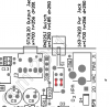
Maybe the picture is not a good way to illustraste the wiring. The + on the picture shows the +board and the - shows the -board. I did not run them on the same board. Just wanted to make sure the wiring is correct and the correct pins are connected.
solderdude
Grand Contributor
On the negative board the wires need to be connected to the other side of R17 and the other side R21 !
So the holes of those resistors being closest to the edge of the board.
So the holes of those resistors being closest to the edge of the board.
OP
Silou
Active Member
- Joined
- Oct 5, 2018
- Messages
- 245
- Likes
- 114
- Thread Starter
- #158
I will change the wiring of R17 and R21 tomorrow and measure U1 again.
I modded my DT770 and K712 in the last days so they can be used balanced. I would like to test with some cheap headphones first. What is the trick you mentioned earlier?
P2 positive board:
pin1: L+
pin2: R+
P2 negative board:
pin3: L-
pin4: R-
I modded my DT770 and K712 in the last days so they can be used balanced. I would like to test with some cheap headphones first. What is the trick you mentioned earlier?
Is that the correct wiring?You can connect the balanced headphone. If you don't have balanced cables yet I will tell a trick how to test the amp (channel by channel) using TRS headphone.
P2 positive board:
pin1: L+
pin2: R+
P2 negative board:
pin3: L-
pin4: R-
solderdude
Grand Contributor
The trick for testing using a cheap headphone with TRS:
R+ to Tip and R- to shield (you will only hear the R channel one the right earpiece)
when that channel works to test the L channel do the same but with L+ to Tip and L- to shield (you will only hear the L channel one the right earpiece)
You can not and must not test L and R at the same time...
When that works you can connect a 4-pin XLR:
R+ = 4 (P2Off Board Output) positive board -> (insert filters here later) -> pin-3 XLR
L+ = 3 (P2Off Board Output) positive board -> (insert filters here later) -> pin-1 XLR
R- = 4 (P2Off Board Output) negative board -> pin-4 XLR
L- = 3 (P2Off Board Output) negative board -> pin-2 XLR
The TRS on the amp will be connected like this:
pin-3 XLR to Ring
pin-1 XLR to Tip
pin 2 from P2Off Board Output positive board (so NOT from the XLR) to Sleeve
Last edited:
solderdude
Grand Contributor
For the filter indication LED do you want to use 4 LEDs (same colour, different colour) that indicates the position or want to use a single 3-color LED and make colours like red, green, blue and purple (or yellow) ?
Similar threads
- Replies
- 29
- Views
- 2K
- Replies
- 20
- Views
- 978
- Replies
- 5
- Views
- 359