• WANTED: Happy members who like to discuss audio and other topics related to our interest. Desire to learn and share knowledge of science required. There are many reviews of audio hardware and expert members to help answer your questions. Click here to have your audio equipment measured for free!

DIY: Summer Projects

OP
Silou

Silou

Active Member
Joined
Oct 5, 2018
Messages
245
Likes
114
Wiring the SMSL M3 board to the O2 is probably not that easy. The M3 has a switch that acts as the power and input selector switch. There is no schematic available. The LEDs indicate the currently used input and the sample rate. The little board is connected with a flat cable to the main board.

IMG_20190825_113120.jpg
 
OP
Silou

Silou

Active Member
Joined
Oct 5, 2018
Messages
245
Likes
114
I just found this to backlight the volpot and the filter selector. It should fit perfectly. There are no white LEDs available, but yellow is my favorite colour anyway :)
 

NTK

Major Contributor
Forum Donor
Joined
Aug 11, 2019
Messages
2,713
Likes
5,999
Location
US East
Wiring the SMSL M3 board to the O2 is probably not that easy. The M3 has a switch that acts as the power and input selector switch. There is no schematic available. The LEDs indicate the currently used input and the sample rate. The little board is connected with a flat cable to the main board.

View attachment 31942
The push button in this little board is read by the microcontroller, and the LED's on the board are also controlled by the microcontroller. Better not mess with it.
 

solderdude

Grand Contributor
Joined
Jul 21, 2018
Messages
16,042
Likes
36,411
Location
The Neitherlands
You want to build the M3 in the same enclosure as the amps instead of the tone board ?

Why would it be difficult to wire the M3 ?
The switch on the front can be replaced by a single pushbutton switch, the outputs wired as you would the tone board and the extra 5V power input socket connected to a 5V adapter (situated inside the enclosure).
 
OP
Silou

Silou

Active Member
Joined
Oct 5, 2018
Messages
245
Likes
114
You want to build the M3 in the same enclosure as the amps instead of the tone board ?

Why would it be difficult to wire the M3 ?
The switch on the front can be replaced by a single pushbutton switch, the outputs wired as you would the tone board and the extra 5V power input socket connected to a 5V adapter (situated inside the enclosure)
Yesterday I had some static noise problems with USB again. I wanted to use the M3 for an other purpose anyway. I will just stick with two analog inputs for the amplifier.

To the LEDs: Where do I get the power for the LEDs? The two signal rings need 12V and the other three LEDs need around 2V. Not sure if I will choose yellow or white LEDs yet.
 

solderdude

Grand Contributor
Joined
Jul 21, 2018
Messages
16,042
Likes
36,411
Location
The Neitherlands
I would use a separate 12V regulator (7812 possibly on a small PCB) and connect that to the smoothing caps of the O2.
So before the 12V regulators on the PCB.

The other LEDs don't need a voltage (like the ring does) but rather need a current.
This current you can make using a resistor.
Problem is the value of those resistor(s) depends on the used LEDs, their color, efficiency and how bright you want them to be so you would have to experiment with that.
I would feed those 3 input LEDs from the same 12V as the LED ring (but WITH resistor(s) in series otherwise they blow up instantly.
 
OP
Silou

Silou

Active Member
Joined
Oct 5, 2018
Messages
245
Likes
114
I will order some LEDs and resistors and decide than.
White 3mm 700mcd 3,1V 20mA 442 Ohm resistor (already have them)
Yellow 3mm 200mcd 2,0V 20mA 499 Ohm resistor
Yellow 3mm 800mcd 2,0V 20mA 499 Ohm resistor
µA 7812 & a small PCB

Is anything else needed?
 

solderdude

Grand Contributor
Joined
Jul 21, 2018
Messages
16,042
Likes
36,411
Location
The Neitherlands
These resistor values you need are definitely not the ones you quoted.
I don't think you are planning to light up the room ;)
They will probably between 2.2k and 100k.
I would look for 2mA LED's as indicators.
Look for a large viewing angle as well.
In order to get them to have a pleasant brightness, which is the same for all indicators, you are going to have to experiment.

I would suggest to buy a 1k resistor + 100k potmeter and visually tune each LED.
Connect the 1k resistor in series with the wiper of the potmeter and use that in series with the LED on 12V.
Ensure you have the polarity correct.
At -12V some LED's may give up their ghost.

The 7812 need input and output decoupling capacitors.
Try to look for a small power supply PCB designed for the 7812.
 
OP
Silou

Silou

Active Member
Joined
Oct 5, 2018
Messages
245
Likes
114
These resistor values you need are definitely not the ones you quoted.
I don't think you are planning to light up the room ;)
They will probably between 2.2k and 100k.
I would look for 2mA LED's as indicators.
Look for a large viewing angle as well.
In order to get them to have a pleasant brightness, which is the same for all indicators, you are going to have to experiment.

I would suggest to buy a 1k resistor + 100k potmeter and visually tune each LED.
Connect the 1k resistor in series with the wiper of the potmeter and use that in series with the LED on 12V.
Ensure you have the polarity correct.
At -12V some LED's may give up their ghost.

The 7812 need input and output decoupling capacitors.
Try to look for a small power supply PCB designed for the 7812.
I have never worked with LEDs before. Did not know that these little 3mm LEDs can get that bright :D
There are not that many 2mA LEDs I can choose from, so I will get this one. I used this calculator to obtain the resistor values mentioned above.
I could not find a fitting power supply yet.

Potentiometer should be mono and linear?
 

solderdude

Grand Contributor
Joined
Jul 21, 2018
Messages
16,042
Likes
36,411
Location
The Neitherlands
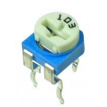
Yes, buy a cheap trimmer pots like these or the one below (the picture shows a 10k pot).
When using different color LEDs buy 3 of them and adjust the brightness.
You can also buy 20mA LEDs though, purple, white, orange, whatever color you like.


RM-065_3.jpg


You can use PCB's like this

All you really need is a TO-220 7812 + 2 ceramic capacitors of 100nF.
Mount these as close as possible to the input and ground pin and the other one between the output and ground.

Another option is to feed it from the already present +12V rail but you should check if the positive regulator does not get too hot (it has quite a bit of voltage across it)
 
Last edited:
OP
Silou

Silou

Active Member
Joined
Oct 5, 2018
Messages
245
Likes
114
Would it be possible to combine the LED signal ring and the volume control? To my understanding a potentiometer changes the resistance from high value up to a low value. It is basically the same with a LED. If the resistor in front of the LED is high, the LED gets less bright than with a lower resistance. I would need a potentiometer with three (or four for both rings?) channels than. Please correct me if I am wrong :)

Is this suitable as LED power supply, or far too powerfull for my purpose?
 

solderdude

Grand Contributor
Joined
Jul 21, 2018
Messages
16,042
Likes
36,411
Location
The Neitherlands
You would need a 4-gang potmeter with A taper and some nifty electronics that would dim the LED ring (PWM most likely) if you want to do this in a nice and relevant way.

Let's just say that I would not build it myself...

I would just use the 12V from the amp.
 
Last edited:
OP
Silou

Silou

Active Member
Joined
Oct 5, 2018
Messages
245
Likes
114
The back panel is almost done. The power socket is currently missing, which leads me to a question. Which parts are supposed to make contact with the chassis? Almost everything I bought is made out of metal and makes contact with the chassis. The power socket will be in the right corner. I will either use plexiglass or a metal sheet to mount it (depends if it is supposed to be grounded to the chassis)
IMG_20190902_160847.jpg
 

solderdude

Grand Contributor
Joined
Jul 21, 2018
Messages
16,042
Likes
36,411
Location
The Neitherlands
When the power socket has a filter in it, the enclosure of the filter (the metal parts) must make contact with the IEC inlet. The ground lug of the IEC inlet also MUST be connected to the chassis.
Audio ground can be connected directly to the chassis or via a resistor with a capacitor in parallel.
 
OP
Silou

Silou

Active Member
Joined
Oct 5, 2018
Messages
245
Likes
114
When the power socket has a filter in it, the enclosure of the filter (the metal parts) must make contact with the IEC inlet. The ground lug of the IEC inlet also MUST be connected to the chassis.
I do not think that there is any filter built into the power socket.
 

solderdude

Grand Contributor
Joined
Jul 21, 2018
Messages
16,042
Likes
36,411
Location
The Neitherlands
Thought you were going in with mains (given the hole).
The low voltage socket mounting ring may not (but could be) connected to the outer contact.
It should not be connected but if this one is (not clear from spec sheet) then the outer contact should be connected to the 'ground' AC input and the center pin to the AC input side.
 
OP
Silou

Silou

Active Member
Joined
Oct 5, 2018
Messages
245
Likes
114
Is there an easy way to test the LED ring?
Can I just use a 12V DC power supply and add a resistor in front of the ring? The ring needs 12V DC and 4,2mA.
 

solderdude

Grand Contributor
Joined
Jul 21, 2018
Messages
16,042
Likes
36,411
Location
The Neitherlands
The 12V DC LED ring does not need any resistors, just 12V. The resistors (or current sources) are already integrated in the wring.
Just connect it to a 12V power supply or the 12V rail inside the O2.
 
OP
Silou

Silou

Active Member
Joined
Oct 5, 2018
Messages
245
Likes
114
The 12V DC LED ring does not need any resistors, just 12V. The resistors (or current sources) are already integrated in the wring.
Just connect it to a 12V power supply or the 12V rail inside the O2.
I thought I would kill it if I connect it to a 5A source :D Thanks I will try it tomorrow
 

solderdude

Grand Contributor
Joined
Jul 21, 2018
Messages
16,042
Likes
36,411
Location
The Neitherlands
Only a single LED would go up in flames (actually explode) when connected without resistors.
Some indicators are specifically designed to work on 5V or 12V, even on 230VAC but these have extra components.
 
Top Bottom