• WANTED: Happy members who like to discuss audio and other topics related to our interest. Desire to learn and share knowledge of science required. There are many reviews of audio hardware and expert members to help answer your questions. Click here to have your audio equipment measured for free!

DIY Push-Pull Subwoofer: Passive M&K MX-5100

kiwifi

Active Member
Joined
Apr 21, 2021
Messages
235
Likes
187
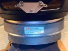
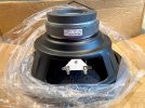
I am planning to build a passive version of the M&K (Miller & Kreisel) MX-5100 (a.k.a. MPS-5420SFSB) using a pair of genuine M&K, brand new (old stock) 17035 "Super Fast" 12" 8ohm drivers that I bought on eBay. The drivers cost 55USD each, but by the time they reach New Zealand they will have cost 150USD each.
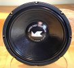
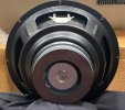
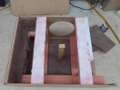
17035-1.jpg17035-2.jpg17035-3.jpg17035-4.jpg

The MX-5100 was the largest 2 x12" sub that M&K made just before they went bankrupt. For that reason they are quite rare, but very well regarded. I'll be using the sub with an external amp and DSP rather than a built in plate amplifier.

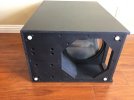
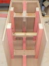
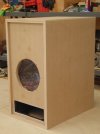
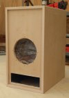
The original cabinet (39cm x 61cm x 79cm) can be found for sale on eBay (search "MPS5160SF"), but shipping a 70lb cabinet to New Zealand is out of the question. The pictures however, were very useful in designing my own version. Note that the original cabinet uses 2x4 timber for internal bracing; this is not a small sub!
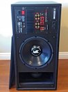
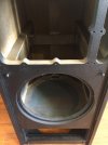
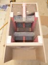
front3.jpgfront1.jpgbot.jpg

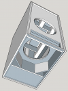
My cabinet design (SketchUp) uses two layers of 12mm MDF sandwiched (glued) together and 2x4 bracing similar to the original, but without the amplifier cutout. The internal dimensions started off as 40cm x 60cm x 80cm (192L) box. I have not calculated the internal volume minus bracing from the model yet, but I estimate it to be about 150L.
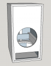
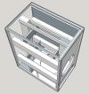
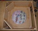
Model_solid.pngModel_sidesCutaway.pngModel_bottomCutaway.png

More to come...
 
OP
kiwifi

kiwifi

Active Member
Joined
Apr 21, 2021
Messages
235
Likes
187
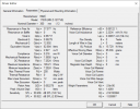
The two M&K 17035 (MK Z-121TV8) have arrived safe and sound in their original M&K factory packaging. I have measured the TS parameters for those who might be interested, but since these are brand new drivers, they are likely to change a little as they loosen up.

R(e) = 7.25ohm, F(s) = 37Hz, Q(ts) = 0.557, Q(es) = 0.583, Q(ms) = 12.69, L(e) = 0.307mH, M(ms) = 85.34 grams, V(as) = 83 liters

TS_17035-1.PNGTS_17035-2.PNG
 

AstroMik

Member
Joined
Apr 22, 2021
Messages
20
Likes
10
G'day Kiwi, Mik from OZ
I always wanted to know whats the M&K subs like... never seen a real test/measurement. I have a few Peerless SLS12 and planing to use them like this push-pull with a Linkwitz transform circuit.. Not as much Xmax but the upper-bass efficiency is similar. So for music the kick-drum will have a good punch. Will not compete with an SVS HT sub below 40Hz on MAX SPL ... but always can double up for more displacement.
Let us know how it turn out your project.
Cheers,
Mik
 
OP
kiwifi

kiwifi

Active Member
Joined
Apr 21, 2021
Messages
235
Likes
187
G'day Kiwi, Mik from OZ
I always wanted to know whats the M&K subs like... never seen a real test/measurement. I have a few Peerless SLS12 and planing to use them like this push-pull with a Linkwitz transform circuit.. Not as much Xmax but the upper-bass efficiency is similar. So for music the kick-drum will have a good punch. Will not compete with an SVS HT sub below 40Hz on MAX SPL ... but always can double up for more displacement.
Let us know how it turn out your project.
Cheers,
Mik
I have only owned M&K 8" push pull subs, so I am looking forward to hearing the twelves. I think that a Linkwitz transform is essential for all but the largest drivers in a sealed cabinet.

Modeling suggests that the internal volume of 140 liters is almost ideal (163L) for a pair of 17035. The resultant total Q of the driver plus cabinet should be close to 0.7.
140L prediction.png

I expect to be able to extend the "anechoic" LF down to 26Hz (F3) with a 12dB (gain) low shelf. Room gain should extend it down further.

Once construction is complete, it's easy to measure the actual Qt & Fs with just an impedance sweep. Then use Qt & Fs to apply the correct LT (PEQ + low shelf) for an additional octave of LF. I'll then use REW & Multi-Sub Optimizer to correct the in room response for a group of seats and finally Audyssey to integrate with the mains.
 
Last edited:
OP
kiwifi

kiwifi

Active Member
Joined
Apr 21, 2021
Messages
235
Likes
187
Construction of the cabinet has started, but is currently on hold while I wait for M5 T-nuts and machine screws to arrive from China...

P1090365.jpegP1090366.jpegP1090367.jpeg
 
OP
kiwifi

kiwifi

Active Member
Joined
Apr 21, 2021
Messages
235
Likes
187
Construction is complete...

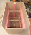
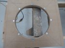
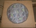
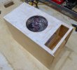
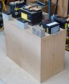
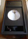
The lower baffle - T-nuts installed and hot glued in place. Edges rounded over. The mesh is to prevent the polyester fill from falling down onto the lower cone. It is taken from a frying pan splash guard. Stapled and hot glued in place.
P1090543.jpegP1090545.jpeg

Checking clearances!
P1090546.jpeg

The interior is lined with woolen felt as the sides are glued and screwed into place.
P1090548.jpegP1090550.jpeg

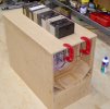
Bracing the lower driver housing.
P1090551.jpeg

A shower cap is used to catch the sawdust that will be generated when the top layer of the front baffle is cut out. The outer layer of 12mm MDF is then glued to the front baffle.
P1090552.jpegP1090553.jpegP1090554.jpeg

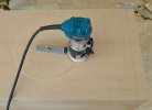
The two openings in the inner layer of the front baffle are used to guide the router on the outer layer using a trim bit.
P1090555.jpegP1090556.jpegP1090557.jpeg

The entire inner 12mm cabinet is wrapped in an outer layer of 12mm MDF. A spreader is used to keep the glue even. Weights and a few brad nails hold it in place while the glue dries, then the edges are trimmed flush with a router.
P1090558.jpeg

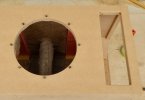
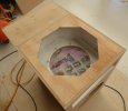
Constructing the octagonal access for the lower driver. It is painted inside before gluing in place.
P1090653.jpegP1090654.jpeg

The top is the last panel to be fitted.
P1090656.jpegP1090657.jpeg

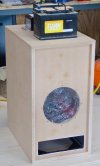
Round off the all the sharp edges, fit the panel (where the amplifier would have been) and undercoat. I have left myself the option to make a baffle cover if necessary.
P1090658.jpegP1090659.jpeg

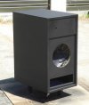
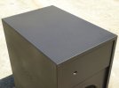
It looked pretty good in white, but I finished it outside in black, spaying an oil based black satin.
P1090660.jpegP1090661.jpeg

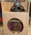
The interior is stuffed with polyester fill and the drivers fitted. The lower driver is wired electrically out of phase with the front one, so that they move in and out together. They can be wired in series or parallel. In my case I went with series to suit the amplifier that I am using.
P1090662.jpeg

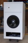
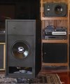
Done! It is very heavy, so I attached a furniture dolly to the base to make it easy to maneuver into position. This had the added advantage of lifting the cabinet a few inches of the ground and allowing sound to exit along the floor, in addition to the top and sides. The cabinet is positioned in a corner, facing into the front wall (about 4 inches away) for maximum room coupling.
P1090663.jpegP1090664.jpeg

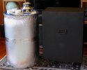
Size comparisons...In the first picture, the sub on the lower right is an SVS PB1000. In the second picture, the MX5100 next to my 200L Barrel Sub, which it has replaced.

Overall it came out slightly larger (850mm x 670mm x 450mm) than the original M&K MX5100, about 50mm more in each dimension.
 
OP
kiwifi

kiwifi

Active Member
Joined
Apr 21, 2021
Messages
235
Likes
187
Looks great!
The sound is...? With what satellites?
Satellites are all M&K S-100B, except for front L/R which are Tannoy System 800. Very happy with the sound so far, with only basic calibration. Measurements to follow - stay tuned!
 
OP
kiwifi

kiwifi

Active Member
Joined
Apr 21, 2021
Messages
235
Likes
187
Some measurements...

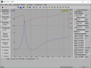
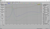
Here is the impedance sweep.
TS_MX5100.PNG

Qt = 0.704 and Fs = 45Hz are pretty much as predicted above. The blue trace is the combined box plus drivers response and the other two traces are the free air responses of each driver for comparison. After a couple of weeks of use, I have noticed that Qt has fallen slightly to 0.66 and Fs is down from 45 to 44Hz. I am assuming this is just due to driver break in.

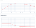
Here is the frequency response measured "Very Near Field" (VNF) both with and without Linkwitz Transform (LT) applied.
VNF.jpgVNF_FR.jpg

Note that the absolute SPL value is not calibrated.
There is a 160Hz 24dB/Oct Butterworth LPF applied to the input signal.
The Linkwitz Transform is simply a Low Shelf at Fc = 22.5Hz (45Hz/2), Q = 0.707 (12dB/Oct), Gain = 12dB.
 

AstroMik

Member
Joined
Apr 22, 2021
Messages
20
Likes
10
Great project mate!
I wonder how the sound of a sealed sub or 3-way Linkwitz Transform compared to a low tuned BR with HP filter to protect the driver?
 
OP
kiwifi

kiwifi

Active Member
Joined
Apr 21, 2021
Messages
235
Likes
187
Great project mate!
I wonder how the sound of a sealed sub or 3-way Linkwitz Transform compared to a low tuned BR with HP filter to protect the driver?
The bass reflex will roll off more quickly below the port tuning frequency. The LT sealed still rolls off at 12dB/Oct same as sealed. With LT you are trading max output for low frequency extension.
 

Juhazi

Major Contributor
Joined
Sep 15, 2018
Messages
1,725
Likes
2,910
Location
Finland
Nice project! My guess is that LT is not needed because of floor/room gain, home environment.
 
OP
kiwifi

kiwifi

Active Member
Joined
Apr 21, 2021
Messages
235
Likes
187
My room is too long for room gain to be a factor.

Here is the in room response of the MX5100 (with LT applied)...
InRoomResponse.png
 
Top Bottom