• WANTED: Happy members who like to discuss audio and other topics related to our interest. Desire to learn and share knowledge of science required. There are many reviews of audio hardware and expert members to help answer your questions. Click here to have your audio equipment measured for free!

DIY Purifi Amp builds

jsy

Member
Joined
Feb 2, 2020
Messages
51
Likes
29
Please don't delete his posts, or Tom's:

a) I found the general discussion about why a builder might want speaker protection in the output path of a power amp informative
b) I don't think there's any risk a reasonable reader would confuse Tom as a shill or "Frankie" as anything but a troll
c) anybody who's made it this far in the thread has survived the multiple science_is_fun debacles. This is a walk in the park
 

G.V.

New Member
Joined
Feb 3, 2020
Messages
1
Likes
0
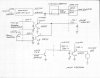
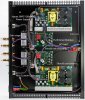
Block diagram for using relay board to enable / disable amp and light switch LED.
Purchased Items
Meanwell – IRM-30-12ST $15 to $17 u.s 12VDC power supply.-DigiKey supply house.
4 Channel 12v relay board sold by VOGURTIME Amazon $7.99.
Quentacy 19mm latching pushbutton switch with 12v LED $9.99 Amazon.
SYSLY IDC 2by5 male header breakout terminal block $13.99 Amazon.
10 pin 3m cable -parts bin.
Screw terminal - parts bin -Homedepot or Lowes.
Ik resistor parts bin.
Jumper from SMPS J5.1 SHE-001T-po.6 6X2 12inch.- Digikey supply house.
If you want a power on switch and remote on you need a “OR” function i.e. remote on OR power switch on. If you only need switch on then you only need a two-channel relay board.
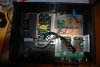
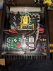
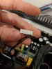
If you have any questions I will try to answer them. Refer to picture to help identify items.

Hello JimM,

Thank you for posting your amp build - it is really helpful!

I have a question, please, excuse me if it is a very silly question - I come from software development background and I am trying to learn electronics:
- could I simply get away by supplying +12V directly to the SMPS Standby J5.1 input? For example, something like this:

standby_circuit.png

^ either the switch or the relay controlled by the external Trigger would interrupt the standby circuit to wake the SMPS up.
I could go even crazier and break the 220V circuit before the AC/DC power supply - in this case the 12V AC/DC power supply would be fully switched-off when the amplifier is operating. Or am I wrong?

Does the J5.1 needs to be pulled down when SMPS is not in the stand-by mode?


I also have a similar question regarding the relay and the AmpOn LED - 100mA max through J4.6 should be enough to directly power a 20mA LED?

I would be very thankful if you spared some time to provide an explanation.

Thank you!

G.V.
 

JimM

Member
Forum Donor
Joined
Jan 7, 2020
Messages
61
Likes
28
Location
New Mexico
Smps needs to be pulled low to enable the power supply I also used a 1k resistor to pull it high as it feeds a 220 ohm resistor which is the input to a opto coupler. In the standby state the J5.1 input is pulled high and needs to be pulled low to enable it. In your drawing if you would tie NO to ground then when the trigger is active i.e. relay active the J5 input will be tied to ground, but you don't want to short the J5 power source to ground with out some resistance to limit the current Which is why I used a 1k resistor to the V+ source. Also the voltage source for the J5 needs to have the same ground reference as the SMPS and needs to be on all the time. To ensure the grounds are the same is why I also used the J4 break out to get to the grounds on J4 to connect to the power supply ground. Yes the transistor output J4.6 is more than enough to drive a LED you must limit the current going to the LED also it is a open collector so it needs a pull resistor to some V+ that also needs to have same ground reference as smps. In my case the LED switch has a built in resistor to limit the current from the 12V supply. I have a simpler circuit using opto couplers that I will check out tomorrow and if ok will post the circuit. Hope this helps and will follow up in a day or so.
JimM
 

JimM

Member
Forum Donor
Joined
Jan 7, 2020
Messages
61
Likes
28
Location
New Mexico
G.V. you can also purchase a remote power strip that has a IR remote to turn it on/off or look at what JimB did in post 166 and just cycle main AC power on to the AMP, I see you reference 220vAC so you may have to look around to find a power strip for Euro 220. But it is a simple solution for remote on/off. I asked the question how many people even turn off the amps as the idle power is very low but did not get any answers. A lot of my equipment in the past I have left powered up in the Idle state except when I would be gone for extended period of time.
JimM
 

MMorrill88

Member
Joined
Feb 4, 2020
Messages
13
Likes
4
Hello everyone I am new to this forum but I recently purchased the purifi Eval1 board and Smps1200A400. I got that up and running without much issue. So I also have Nord One SE NC500 MKII in mono block form with Rev D boards. I emailed Colin asking if the Rev D for NC500 works with 1ET400A module, and he said yes it works. So I inserted the Purifi module into the rev d board but no sound came out, and nothing got damaged either. I was wondering if anyone in here knows what I possibly did wrong? Only thing that was not the same with the nc500 board was the screws holding it in on the bottom of the case, could this be that important?
 

boXem

Major Contributor
Audio Company
Joined
Jun 19, 2019
Messages
2,018
Likes
4,899
Location
Europe
Hello everyone I am new to this forum but I recently purchased the purifi Eval1 board and Smps1200A400. I got that up and running without much issue. So I also have Nord One SE NC500 MKII in mono block form with Rev D boards. I emailed Colin asking if the Rev D for NC500 works with 1ET400A module, and he said yes it works. So I inserted the Purifi module into the rev d board but no sound came out, and nothing got damaged either. I was wondering if anyone in here knows what I possibly did wrong? Only thing that was not the same with the nc500 board was the screws holding it in on the bottom of the case, could this be that important?
What SMPS are you using? The one you purchased?
Boards should be well screwed for proper cooling, but that doesn't prevent them from running.
 

MMorrill88

Member
Joined
Feb 4, 2020
Messages
13
Likes
4
With the Eval1 board I am using SMPS1200A400. Inside the Nords they are also SMPS1200A400, I was just trying to see if I could do a direct swap to run the Purifi in monoblock form.
 

JimM

Member
Forum Donor
Joined
Jan 7, 2020
Messages
61
Likes
28
Location
New Mexico
Finished the simplified circuit, parts list is the same with the exception of the 4N35 optocouplers and sockets plus proto boards. This replaces the 4 channel relay board. Both methods work well so It’s just a matter of preference. I have not had any problems with either one but proceed at your own risk. Will show a picture of the new version which is a little less cluttered, I used two separate proto boards to split up the two functions SMPS standby and LED amp enable. So now need to set back and enjoy. Thanks again for all the help, at this time it is one of my favorite amps.
JimM
 

Attachments

  • sch no2 Purifi io.jpg
    sch no2 Purifi io.jpg
    1.1 MB · Views: 785
  • DSC_0100.JPG
    DSC_0100.JPG
    4 MB · Views: 710
  • DSC_0102.JPG
    DSC_0102.JPG
    3.3 MB · Views: 562

boXem

Major Contributor
Audio Company
Joined
Jun 19, 2019
Messages
2,018
Likes
4,899
Location
Europe
With the Eval1 board I am using SMPS1200A400. Inside the Nords they are also SMPS1200A400, I was just trying to see if I could do a direct swap to run the Purifi in monoblock form.
Are you sure it's not a SMPS1200A700? Then the modules would be in overvoltage.
 

mocenigo

Major Contributor
Joined
Dec 8, 2018
Messages
1,288
Likes
1,052
Hello everyone I am new to this forum but I recently purchased the purifi Eval1 board and Smps1200A400. I got that up and running without much issue. So I also have Nord One SE NC500 MKII in mono block form with Rev D boards. I emailed Colin asking if the Rev D for NC500 works with 1ET400A module, and he said yes it works. So I inserted the Purifi module into the rev d board but no sound came out, and nothing got damaged either. I was wondering if anyone in here knows what I possibly did wrong? Only thing that was not the same with the nc500 board was the screws holding it in on the bottom of the case, could this be that important?

The Purifi modules will not work with a SMPS1200A700, which provides 84V. As soon as the voltage is higher than 72 (IIRC) they will just stop working, without damage. So you cannot use the Purifi modules in the Nord monos, but you could take them out and connect everything with the SMPS1200A400 (which will require and additional cable set and a bit of surgery)
 

barrows

Active Member
Joined
Jan 24, 2020
Messages
150
Likes
219
You are probably right just checked Nords website!

I am looking forward to hearing your thoughts regarding the Purifi modules with the eval board vs. the mono config with your Nord Rev D gain stages! Please post impressions when you get it running, I am OK with a subjective opinion of relative sound quality.
 

MMorrill88

Member
Joined
Feb 4, 2020
Messages
13
Likes
4
I am looking forward to hearing your thoughts regarding the Purifi modules with the eval board vs. the mono config with your Nord Rev D gain stages! Please post impressions when you get it running, I am OK with a subjective opinion of relative sound quality.
I'll see if I end up doing it. I suppose I could just get another smps1200a400 and try it. I'll let you guys know here if I do
 

MMorrill88

Member
Joined
Feb 4, 2020
Messages
13
Likes
4
So here is the Nord with SMPS1200A400 and Purifi 1ET400A installed. I swapped out the nc500 and A700 power supply. I still do not have sound from this channel, have not taken apart the other monoblock yet. I'm not sure what is wrong, maybe someone here does. All the connectors are the same for the power supplies so they just plugged right in. Nord replied to me saying the Rev D is plug and play but maybe I missed some small detail in the pinout?
 

Attachments

  • IMG_20200207_204007.jpg
    IMG_20200207_204007.jpg
    2.6 MB · Views: 469

JimM

Member
Forum Donor
Joined
Jan 7, 2020
Messages
61
Likes
28
Location
New Mexico
Is the SMPS power supply enabled, do you have the +/- 64volts and I don't know if you have to strap the SMPS to unregulated like you do the for the eval unit? Jumper setting on SPMS (Vaux or Vaux,reg) J6 and J7 position 1-2 Regulated Vaux,reg or position 2-3 Unregulated Vaux. Just a thought.
Jim
 

JimM

Member
Forum Donor
Joined
Jan 7, 2020
Messages
61
Likes
28
Location
New Mexico
Also remember the EVal board has a switch to enable the SMPS J5.1 SMPS standby which needs to be logic low to enable the SMPS. I you do not have the +- 64 volts dc on J1.2 and J1.5 that's most likely the problem, need to ground J5.1
Jim
 

JimM

Member
Forum Donor
Joined
Jan 7, 2020
Messages
61
Likes
28
Location
New Mexico
I can't tell looking at picture but it doesn't look like j5.1 has any thing connected to it, but it could be connected through the main connector just don't know, any way worth checking.
Jim
 

MMorrill88

Member
Joined
Feb 4, 2020
Messages
13
Likes
4
Thanks for the reply Jim. Here is a picture of the J5, pin 1 is not connected to anything like you assumed, so this must be grounded? I'm at work right now so when I get home I'll do some checks with the multimeter.
 

Attachments

  • IMG_20200208_063722.jpg
    IMG_20200208_063722.jpg
    2 MB · Views: 295
Last edited:

MMorrill88

Member
Joined
Feb 4, 2020
Messages
13
Likes
4
I'm trying to compare it to this picture from the Nord Three 1ET400A duel mono tear down.
 

Attachments

  • Nord Three SE 1ET400A Dual Mono Stereo Amp With  Sonic Imagery 990Enh Teardown.jpg
    Nord Three SE 1ET400A Dual Mono Stereo Amp With Sonic Imagery 990Enh Teardown.jpg
    178 KB · Views: 515

barrows

Active Member
Joined
Jan 24, 2020
Messages
150
Likes
219
Thanks for the reply Jim. Here is a picture of the J5, pin 1 is not connected to anything like you assumed, so this must be grounded? I'm at work right now so jumpers on the when I get home I'll do some checks with the multimeter.

At this point I would take the meter and check that the appropriate voltages are on the pins of the between board connector vis a vis the Purifi data sheet. I ma sure there is something simple going on here. The Nord input board does use the the unregulated voltage from the SMPS +/- 18 VDC just like the eval board, as it has its own discrete regulators onboard for that supply, so make sure your jumpers in the SMPS 1200A400 are set to the unregulated position. If they are set to regulated, then the regulators on the Nord input board will drop out, and the Purifi module will probably stay shut off due to incorrect voltage for the modulator section.
 
Top Bottom