
-
WANTED: Happy members who like to discuss audio and other topics related to our interest. Desire to learn and share knowledge of science required. There are many reviews of audio hardware and expert members to help answer your questions. Click here to have your audio equipment measured for free!
You are using an out of date browser. It may not display this or other websites correctly.
You should upgrade or use an alternative browser.
You should upgrade or use an alternative browser.
DIY Purifi Amp builds
- Thread starter JimB
- Start date
Got 12 volt remote, and or switch connected to SMPS stand-by/enable and feedback on switch LED with amp enable all off the SMPS works great, turn and turnoff pop free. Decided to use SMPS amp enable J4.6 as a feed back for LED turn-on rather than EVAL1 ready signal, a it's cheaper to replace SMPS than EVAL1 if something did not go right, and it will be obvious if the amps don't come on. Used a 4 channel relay board with opto -coupler inputs, wiring is a mess so will design and build a prototype board to see if can clean up some of the wiring and simplify the circuity. Driving my 3way Jeff Bagby design Kairos speakers I think I like this combination even better than than the Maggies so great project. Thanks again for all the input.
JimM
JimM
Attachments
What gets you the pop free start of you're using the amp enable output from the SMPS to drive the led on the front? Or is it controlling both the LED and the Eval1 board. Clearly I'm misunderstanding something.Got 12 volt remote, and or switch connected to SMPS stand-by/enable and feedback on switch LED with amp enable all off the SMPS works great, turn and turnoff pop free. Decided to use SMPS amp enable J4.6 as a feed back for LED turn-on rather than EVAL1 ready signal, a it's cheaper to replace SMPS than EVAL1 if something did not go right, and it will be obvious if the amps don't come on. Used a 4 channel relay board with opto -coupler inputs, wiring is a mess so will design and build a prototype board to see if can clean up some of the wiring and simplify the circuity. Driving my 3way Jeff Bagby design Kairos speakers I think I like this combination even better than than the Maggies so great project. Thanks again for all the input.
JimM
Would love if you could do a basic wiring diagram so I could understand the whole picture. Not that it's your job to EILI5
")
Nice work!
Got 12 volt remote, and or switch connected to SMPS stand-by/enable and feedback on switch LED with amp enable all off the SMPS works great, turn and turnoff pop free. Decided to use SMPS amp enable J4.6 as a feed back for LED turn-on rather than EVAL1 ready signal, a it's cheaper to replace SMPS than EVAL1 if something did not go right, and it will be obvious if the amps don't come on. Used a 4 channel relay board with opto -coupler inputs, wiring is a mess so will design and build a prototype board to see if can clean up some of the wiring and simplify the circuity. Driving my 3way Jeff Bagby design Kairos speakers I think I like this combination even better than than the Maggies so great project. Thanks again for all the input.
JimM
What's the purpose of the relay board in your build? Is it to delay turning on and off the various supplies?
You could use something like my Modulus-86 or Modulus-186 with a ±24 V power supply and have plenty of power available for the horn drivers. Just saying.
And nobody says that this is not on my list of projects for the future
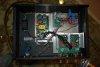
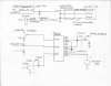
The pop free I believe is a function of the SMPS turn on and turn off i.e. the SMPS enable. I used the relay board as it was convenient with screw terminals to prove the concept. The relay board has optocouplers for input so you get isolation on the input side and the relays provide isolation on the out put plus you get either normally closed or normally open for polarity. The problem using the relay board is the nest of wires. There is no delay with the relay board but the SMPS does have delay with the enable / disable. If you look at the picture there is also a meanwell 12VDC supply that remains on when AC power is applied to the chassis and this provides the external supply for standby mode. I used the smps amp on signal to light the LED as a feed back to show the SMPS and the EVAL has power applied. I am currently designing and will prototype a bread board using some TTL logic that I have in parts bin to create a simpler circuit. I will draw up a block diagram using the relay board and see if I get it to post. And at some point will show bread board circuit when get it finished and checked out.
JimM
JimM
I used the relay board as it was convenient with screw terminals to prove the concept. The relay board has optocouplers for input so you get isolation on the input side and the relays provide isolation on the out put plus you get either normally closed or normally open for polarity.
I am still not 100% sure I understand the role of the relay board, then. When the amp is in standby the relays are open, so no current passes?
Anyway, to distribute the current I am using these handy busbars and they help a lot keeping everything clean.
Block diagram for using relay board to enable / disable amp and light switch LED.
Purchased Items
Meanwell – IRM-30-12ST $15 to $17 u.s 12VDC power supply.-DigiKey supply house.
4 Channel 12v relay board sold by VOGURTIME Amazon $7.99.
Quentacy 19mm latching pushbutton switch with 12v LED $9.99 Amazon.
SYSLY IDC 2by5 male header breakout terminal block $13.99 Amazon.
10 pin 3m cable -parts bin.
Screw terminal - parts bin -Homedepot or Lowes.
Ik resistor parts bin.
Jumper from SMPS J5.1 SHE-001T-po.6 6X2 12inch.- Digikey supply house.
If you want a power on switch and remote on you need a “OR” function i.e. remote on OR power switch on. If you only need switch on then you only need a two-channel relay board.
If you have any questions I will try to answer them. Refer to picture to help identify items.
Attachments
The relay board is just one way to create a OR function for two different ways to use the Hypex SMPS1200A400 SMPS standby input to turn the SMPS power supply on/off in a controlled manner. The input is located on SMPS J5 pin 1. When this input is low the SMPS is enabled. Hypex has a optocoupler on this input to help isolate the interface with the controller. If you use another power supply other than Hypex it will not be the same.
Hope this helps let me know if you more questions.
Hope this helps let me know if you more questions.
You could also use something like my Guardian-686: https://neurochrome.com/products/guardian-686The pop free I believe is a function of the SMPS turn on and turn off i.e. the SMPS enable. I used the relay board as it was convenient with screw terminals to prove the concept.
Tom
Block diagram for using relay board to enable / disable amp and light switch LED.
Purchased Items
Meanwell – IRM-30-12ST $15 to $17 u.s 12VDC power supply.-DigiKey supply house.
4 Channel 12v relay board sold by VOGURTIME Amazon $7.99.
Quentacy 19mm latching pushbutton switch with 12v LED $9.99 Amazon.
SYSLY IDC 2by5 male header breakout terminal block $13.99 Amazon.
10 pin 3m cable -parts bin.
Screw terminal - parts bin -Homedepot or Lowes.
Ik resistor parts bin.
Jumper from SMPS J5.1 SHE-001T-po.6 6X2 12inch.- Digikey supply house.
If you want a power on switch and remote on you need a “OR” function i.e. remote on OR power switch on. If you only need switch on then you only need a two-channel relay board.
If you have any questions I will try to answer them. Refer to picture to help identify items.
Wow this block diagram is amazing. Thanks for taking the time to publish that. I had definitely been wondering about tying the grounds together between the two power supplies so that the standby voltage had the same reference as the SMPS, I see that was achieved through the breakout board. Thanks for posting that.
You could also use something like my Guardian-686: https://neurochrome.com/products/guardian-686
Very interesting. Is there also a kit for the stereo/dual mono version (such as a mouser part list)?
The Guardian-686 is for use with amplifiers that have balanced/bridged/BTL outputs, such as the Hypex/Purifi amps. You can build it as a stereo or dual-mono board as well.Very interesting. Is there also a kit for the stereo/dual mono version (such as a mouser part list)?
The Guardian-86 is a mono version of the same circuit.
All my boards come with extensive design documentation, which includes a BOM and a link to a project set up with Mouser Electronics for ease of ordering parts. Click the links. Select the number of "projects" (= boards) you need parts for. Click "add to cart", and check out as you would at any other online store. A few days later a box of goodies shows up on your doorstep. It's almost as easy as buying a kit.
Tom
Maybe a definition issue here, but as far as I remember, the "minus" output of Hypex/Purifi amps is grounded. So not what I call balanced/bridged/BTL.The Guardian-686 is for use with amplifiers that have balanced/bridged/BTL outputs, such as the Hypex/Purifi amps.
Um. No. The Hypex NC500 data sheet specifically states to NOT connect OUT- to ground.
The Purifi 1ET400A data sheet says OUT- is internally connected to ground.
The NC500 and 1ET400A appear to be very close to identical. Yet, the more I dig into the data sheet, the more subtle differences I find. I suppose the implications of this is that you can use the Guardian-86 or half of a Guardian-686 with the Purifi 1ET400A, but not with the Hypex NC500.
Tom
Attachments
Unless the NC500 OUT- is not to be connected to GND because it's internally connected . Bruno's designs are usually single ended.
Anyhow, since I was still lost, so I had a look at your Guardian-686 page and discovered that it can be used for a stereo single ended amp. The use case here would be for people not wanting to use the SMPS1200 soft start feature right?
. Bruno's designs are usually single ended.Anyhow, since I was still lost, so I had a look at your Guardian-686 page and discovered that it can be used for a stereo single ended amp. The use case here would be for people not wanting to use the SMPS1200 soft start feature right?
If so, they would have said so in the data sheet. Just as they do in the Purifi data sheet. I design by the information in the data sheet. Not by "so-and-so on the internet said" or assumptions. You're free to design your circuits differently.Unless the NC500 OUT- is not to be connected to GND because it's internally connected
Tom
Let's stop the discussion here. I have my own ethics and will stick to them.If so, they would have said so in the data sheet. Just as they do in the Purifi data sheet. I design by the information in the data sheet. Not by "so-and-so on the internet said" or assumptions. You're free to design your circuits differently.
Tom
I apologize if I was perceived as crass. That wasn't my intent. All I intended to say was that I follow the recommendations of the manufacturer. I do recognize that others may have their reasons for designing their products differently, and they are free to do so at their own risk. That's all.
Based on the manufacturer's recommendations, I recommend the Guardian-686 for use with the Hypex NC500 and the Guardian-86 (or half of a Guardian-686) for use with the Purifi 1ET400A.
Tom
Based on the manufacturer's recommendations, I recommend the Guardian-686 for use with the Hypex NC500 and the Guardian-86 (or half of a Guardian-686) for use with the Purifi 1ET400A.
Tom
Similar threads
- Replies
- 0
- Views
- 537
- Replies
- 3
- Views
- 1K