• WANTED: Happy members who like to discuss audio and other topics related to our interest. Desire to learn and share knowledge of science required. There are many reviews of audio hardware and expert members to help answer your questions. Click here to have your audio equipment measured for free!

DIY Mini-Unity Horn. Am I crazy?

OP
A

AwesomeSauce2015

Active Member
Joined
Apr 14, 2022
Messages
204
Likes
195
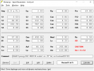
I sort of figured out Hornresp... Turns out the help file is actually useful if I am stuck lol.

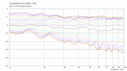
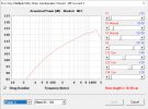
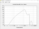
On the upside, if I simulated it correctly, I should be able to hit my SPL target. Hornresp seems to think that if I slam >500w into 4 B&C 4NDF34-8, then I'll get around 120db as I approach 1khz, where I then will cross over to the DE250. Of course, the DE250 will hardly be breaking a sweat at 120db, whereas the midranges will be a molten mess...

The main issue is that since the horn is so small, I get no loading below 900hz. Hence, my need for insane amounts of woofer displacement.

I will probably redo the simulation with larger drivers and entry ports further down the horn.

Edit: I think I finally know the answer to the thread's main question: Yes, I am officially crazy for thinking this is possible! But, with a liberal application of POWAHHH I think it's doable.
 

fluid

Addicted to Fun and Learning
Joined
Apr 19, 2021
Messages
694
Likes
1,198
500W does not make sense to me. The drivers are 90dB for 1 watt, with 4 of the on a flat baffle that is 99dB per watt without constructive interference to get to 120dB needs 128W.

Placed within 1/4 wavelength each driver should increase SPL by 6dB which is quite possible up to 1K, add some compression loading and it should not take as much.

What did you input into Hornresp?
 

kipman725

Active Member
Joined
Jul 6, 2020
Messages
255
Likes
224
I agree I think you would find the DE250 a hot mess at 120dB/1m and the 4NDF34-8 doing fine. Perhaps your not taking into account that Hornresp gives power response and not on axis frequency response?

if you do a simple infinite baffle simulation of the 4NDF34-8 you should see around the datasheet sensitivity which is usualy a 2pi measurement (on IEC test baffle).
 
Last edited:
OP
A

AwesomeSauce2015

Active Member
Joined
Apr 14, 2022
Messages
204
Likes
195
I agree I think you would find the DE250 a hot mess at 120dB/1m and the 4NDF34-8 doing fine. Perhaps your not taking into account that Hornresp gives power response and not on axis frequency response?

if you do a simple infinite baffle simulation of the 4NDF34-8 you should see around the datasheet sensitivity which is usualy a 2pi measurement (on IEC test baffle).

So I'm familiar with the idea of power vs on-axis response, but how would that skew the data I am getting?
Or would that value be more indicative of room response?

What did you input into Hornresp?

I have attached screenshots of the hornresp input. I put in the parameters for the B&C drivers except for Cms and Rms, which weren't on B&C's datasheet (Or I didn't see them). I had hornresp calculate those values from the other ones.

The horn segment dimensions were obtained from the Synergy Calc v5 excel sheet someone posted earlier. (Screenshot attached below)

I then kinda just guessed on the back chamber and port dimensions for the woofers, until I got to what looked like good performance. The port length was fixed, however, at around 0.5-0.75".

B&C Datasheet link:
https://www.parts-express.com/pedocs/specs/294-5938--bc-speakers-4ndf34-8-spec-sheet.PDF

Thanks!
-Me
 

Attachments

  • Hornresp record 2.PNG
    Hornresp record 2.PNG
    49.1 KB · Views: 90
  • Hornresp Woofer Record.PNG
    Hornresp Woofer Record.PNG
    46.5 KB · Views: 90
  • SynergyCalc Values.PNG
    SynergyCalc Values.PNG
    67.4 KB · Views: 84
  • Hornresp woofers 500w.PNG
    Hornresp woofers 500w.PNG
    66 KB · Views: 95

nc535

Member
Joined
Dec 30, 2021
Messages
52
Likes
62
I attached my archive HR record for 4 NDF34s on a larger, 60x60 horn. It gives nice, reasonable output. Change horn parameters to yours ...
 

Attachments

  • 4NDF34on60x60.txt
    1 KB · Views: 77
OP
A

AwesomeSauce2015

Active Member
Joined
Apr 14, 2022
Messages
204
Likes
195
I imported the record you attached, and put in my horn parameters. After fooling around with some of the other dimensions (rear chamber, port dimensions), I arrived at the attached response & parameters. (NOTE: I changed the radiation angle to 4pi to be consistent with the previous one)

After setting both this record and my previous one to 2.83v, this one measured about 4db higher @ 1khz than the previous one.

It must be due to either different driver parameters, or slight changes in the port size.

Any thoughts? When I plug in high power into this simulation, I get much higher SPL output, which is promising.
Also, does anyone know how to decipher the "Acoustic Impedance" graph? It seems as that shows the loading of the woofer drivers, but I don't understand it.
 

Attachments

  • 1651866846677.png
    1651866846677.png
    40.9 KB · Views: 72
  • 1651866861048.png
    1651866861048.png
    60.4 KB · Views: 70

gnarly

Major Contributor
Joined
Jun 15, 2021
Messages
1,015
Likes
1,429
Hi, fwiw here's the raw response of four NDF34's on a fairly large 36"x22" 90x60 horn.
Their ports have centers 3.5" from CD mounting flange.
I don't think the horn size contributes much to any lower end loading....compared to them on smaller horns...
I think you will definitely need ports centers closer to CD if you want to reach higher in freq than shown response.
They should have no problem with the SPL you seem to have in mind...
Good luck !
syn9x75 mid raw 10d corner deck.JPG
 
OP
A

AwesomeSauce2015

Active Member
Joined
Apr 14, 2022
Messages
204
Likes
195
Thanks for showing that!
I'm probably going to end up 3d-printing the first segment of the horn with the driver mounts to get the ports very close to the CD... 1.5-2"
Definitely a larger horn there, looks almost reminiscent of what happens when I crank up the horn size on my models, so that's good...

Out of curiosity what CD are you using and is it a 3-way design you have there?
 

gy-k

Member
Joined
Oct 25, 2021
Messages
39
Likes
22
The BMS 4550 is what could be called the 'original' Synergy Horn CD, right? It's capable of low xo, stated officially on the spec sheet. (I think I've read somewhere that its FR around 1kHz has a shape to it that is used in Danley's designs. Just saying, not necessarily important overall.)

If I'd have to guess, 1kHz should be the target for the xo, and if I'd have to guess right now, 1kHz is probably too high for most 6.5" drivers, the cut-off the mid's band-pass you can actually build would be around that frequency I guess, so I think this points to using 5.5" drivers.
 

nc535

Member
Joined
Dec 30, 2021
Messages
52
Likes
62
I imported the record you attached, and put in my horn parameters. After fooling around with some of the other dimensions (rear chamber, port dimensions), I arrived at the attached response & parameters. (NOTE: I changed the radiation angle to 4pi to be consistent with the previous one)

After setting both this record and my previous one to 2.83v, this one measured about 4db higher @ 1khz than the previous one.

It must be due to either different driver parameters, or slight changes in the port size.

Any thoughts? When I plug in high power into this simulation, I get much higher SPL output, which is promising.
Also, does anyone know how to decipher the "Acoustic Impedance" graph? It seems as that shows the loading of the woofer drivers, but I don't understand it.
If you indeed want very high max SPL ~116 db or so, then I agree with your port diameter and length. If this is for home use you could shrink the port hole area by a factor of 4, which would result in better polars because those large port holes do disrupt the pattern.

Also you should adjust the horn entry point to where the steep drop in output occurs just above your target XO frequency.

The acoustic Z chart is indeed hard to interpret. Reflections from the horn throat and the mouth (it is driven from S2) account for the wild swings. If you model the same horn driven from its throat, you will see something more intuitive. There you will just have mouth reflections of (hopefully much) smaller magnitude
 

gnarly

Major Contributor
Joined
Jun 15, 2021
Messages
1,015
Likes
1,429
Thanks for showing that!
I'm probably going to end up 3d-printing the first segment of the horn with the driver mounts to get the ports very close to the CD... 1.5-2"
Definitely a larger horn there, looks almost reminiscent of what happens when I crank up the horn size on my models, so that's good...

Out of curiosity what CD are you using and is it a 3-way design you have there?
Using a bms 4594he CD.
The design is a 4-way (if you count the two CD sections)...probably best described as a 3-way ignoring that.

It's giving me a lot of room to play with what drivers work best, with what xover frequencies and slopes.
The CD reaches down to 500Hz, The mids, NDF34's, from 180-1000Hz, and the lows 10pr320s from 125 to 500Hz.
So no necessity to use the mids at all....

The wide overlap has let me play with shallower xover slopes to make sure I havent been leaving something on the table with steep linear phase xovers i always use on synergies. So far, low order has sucked big time compared to my usual...(kinda glad to see that really :)
The other optimization area has been how low to take the CD.... I like using the mids up to 900-1000Hz better than taking the CD down lower.

In case you were curious...
syn10 raw set 1-3 oct.JPG
 

nisse.P

Member
Joined
May 7, 2022
Messages
6
Likes
5
I would take ispiration from Danleys studio speaker if I was you.
A nice pro coaxial with a center horn that you drill enough small holes in to. The combined area should be enough for the midrange but not to big to mess up the compression driver response.
Fig 9 in this patent from Carvin Vega is a nice representation https://patentimages.storage.googleapis.com/a9/66/9f/7de4fe52499c91/US4283606.pdf

And Pk-sound did a nice implementation/research about the least intrusive way of porting a midrange to a waveguide http://pro-pa.com/index.php?id=2059
Edit: Patent: https://patentimages.storage.googleapis.com/c8/cb/3c/ebd90aeb6f3761/US9894433.pdf

Extend the horn flare to a ball around the cone driver to maximize smoothness of axis.
This driver would be a really nice candidate https://www.oberton.com/en/products/neodymium-coaxials/465-8nmb250vcx.html?showall=1
The compression driver was tested by Voice coil magazine if you like a more in depth review.
Edit: https://audioxpress.com/article/test-bench-oberton-nd45-pro-sound-compression-driver
And the driver is used in https://dynamikks.de/athos-10-kopie.html
 
Last edited:

crazycloud

Member
Joined
Oct 9, 2021
Messages
81
Likes
151
Using a bms 4594he CD.
I'm contemplating a very similar build to this, but short term using the ROSSO-65CDN-T and moving them onto the small PA enclosures later when I can afford some 4594HE. Do you know what the exit angle of the BMS is?
 
OP
A

AwesomeSauce2015

Active Member
Joined
Apr 14, 2022
Messages
204
Likes
195
Update: I have been working on trying to model the horn in Solidworks to see how it'll fit into a potential enclosure. It has not been easy trying to figure out how to interpret the hornresp values / Synergy Calc excel sheet numbers and put them into SW.

One thing I have settled on is that the horn will most likely have a 90 x 45 degree coverage angle, as that will allow me to mount a woofer below the horn without having a crazy tall speaker. It will also help tame some ceiling / floor bounce.

I'm debating just ignoring what Synergy calc says, and just modeling a horn with straight sides at the size and angles I want. This is because the woofer drivers won't really be loaded at all by the horn, so I don't see the need for the typical flare change of many constant directivity designs, and I already have a decent idea of how big to make the horn in order to properly load the tweeter.

Can someone point me to why exactly constant directivity horns have a flare change towards the mouth of the horn?

... Maybe a "normal" 2-way MTM would be better... lol
Or if someone can point me towards a pro coax driver with a constant directivity pattern, that would probably work too...
 
Last edited:

fluid

Addicted to Fun and Learning
Joined
Apr 19, 2021
Messages
694
Likes
1,198
Can someone point me to why exactly constant directivity horns have a flare change towards the mouth of the horn?
Conical horns have constant directivity from the straight walls. The reason a secondary flare can be useful is that it creates a more gradual termination to the horn which reduces diffraction. In an asymmetric horn it also helps to reduce pattern flip.

Keele has a paper where this is explained

https://www.xlrtechs.com/dbkeele.co...AES Preprint) - Whats So Sacred Exp Horns.pdf

Simulation results below to show the difference of adding a secondary flare.
 

Attachments

  • 2flnorm20.png
    2flnorm20.png
    34.2 KB · Views: 118
  • 50x50 secondary flare.png
    50x50 secondary flare.png
    72.3 KB · Views: 130
  • Secondarymesh.png
    Secondarymesh.png
    221.5 KB · Views: 141
  • 50x50 Vacs.png
    50x50 Vacs.png
    78.1 KB · Views: 120
  • 50x50 mesh.png
    50x50 mesh.png
    538.7 KB · Views: 124
OP
A

AwesomeSauce2015

Active Member
Joined
Apr 14, 2022
Messages
204
Likes
195
Once again, it looks as if I have some reading to do!

Update 2 today: I'm currently thinking about the Eminence BETA-8CX coax driver as it apparently uses a conical horn under the dustcap for the compression driver.
Winisd says that although the bass is xmax limited, it should be easily capable of high enough output > 200hz to keep up with a CD.
That driver + the JBL 2408h-2 with an xover around 1.8khz should be pretty sweet...
That CD is used in the PRX812 with xover @ 1.85khz, so it should be fine going that low.
 

gy-k

Member
Joined
Oct 25, 2021
Messages
39
Likes
22
Once again, it looks as if I have some reading to do!

Update 2 today: I'm currently thinking about the Eminence BETA-8CX coax driver as it apparently uses a conical horn under the dustcap for the compression driver.
Winisd says that although the bass is xmax limited, it should be easily capable of high enough output > 200hz to keep up with a CD.
That driver + the JBL 2408h-2 with an xover around 1.8khz should be pretty sweet...
That CD is used in the PRX812 with xover @ 1.85khz, so it should be fine going that low.

Do you mean using that 8" coax "synergized", i.e. a Synergy horn but with the cone of the coax being the mid instead of separate cone drivers. 8" is going to need a lower xo, because for a larger cone, the band-pass chamber one can actually construct is going to have a lower roll-off.

I think Danley use Beyma 6" and BMS 5" coax drivers this way. By the way I remember someone wrote in the ATH4 thread on Diyaudio, that BMS ring radiators are reputed to have a spherical wavefront, if so, that would be theoretically a good fit for a conical horn, but I'm just guessing.
 
OP
A

AwesomeSauce2015

Active Member
Joined
Apr 14, 2022
Messages
204
Likes
195
@gy-k

No, I literally mean a normal implementation of an 8" coax pro driver.
The problem I'm facing is that in order to get halfway decent bass extension I need a >=6.5" driver, while in order to get proper spacing in a synergy horn I need 4" drivers.
Additionally, for a compact enclosure, the horn takes up a large percentage of the available volume.
With something like the 8" eminence driver, in the form factor I'm looking at, I can easily have dedicated bass drivers in the enclosure, as well as a basically-point-source mid-high unit.
The only major compromise of this design vs a synergy horn would be the potential for beaming of the woofer as it approaches x-over, but that would be a compromise worth living with for a significantly smaller speaker with similar output capacity to the original idea.
 

gy-k

Member
Joined
Oct 25, 2021
Messages
39
Likes
22
The HF driver in the BMS 10C262 is specced in the datasheet as 1000-20000Hz, recommended xo 1200Hz. Such an xo frequency, say 1100Hz would be a pretty good one, as in same beam width of LF and HF. Based on the TS params, and if define 3 for the value of Ql, which is said to model an aperiodic vent, the response is Qtc=0.57 Fb=127 in 9l volume. (Seems good for a 2nd order 180Hz xo.)
 
Last edited:
Top Bottom