• WANTED: Happy members who like to discuss audio and other topics related to our interest. Desire to learn and share knowledge of science required. There are many reviews of audio hardware and expert members to help answer your questions. Click here to have your audio equipment measured for free!

DIY interconnect XLR cables using three wires: how do I twist them?

JensenW

Member
Joined
Jan 3, 2022
Messages
48
Likes
10
I've read other posts on ASR about twisting / braiding for RCA/ headphone cables, as well as the impressive youtube video on audiouniversity channel demostrating much reduced noise with twisted pairs.

I am interested in making a pair of balanced XLR interconnects. I have more than enough cheap bare wires and teflon tubings people threw out. However, I have no braided shield on my hands right now, so I would like to use three wires for the XLR. I'm using them at home, so noise isn't a very big concern.

1. Should I twist all three wires in the same direction? Or should I braid them? Will this be WORSE then twisted pair plus braided shield? If three wires is worse, then I'd better buy some braided shield.

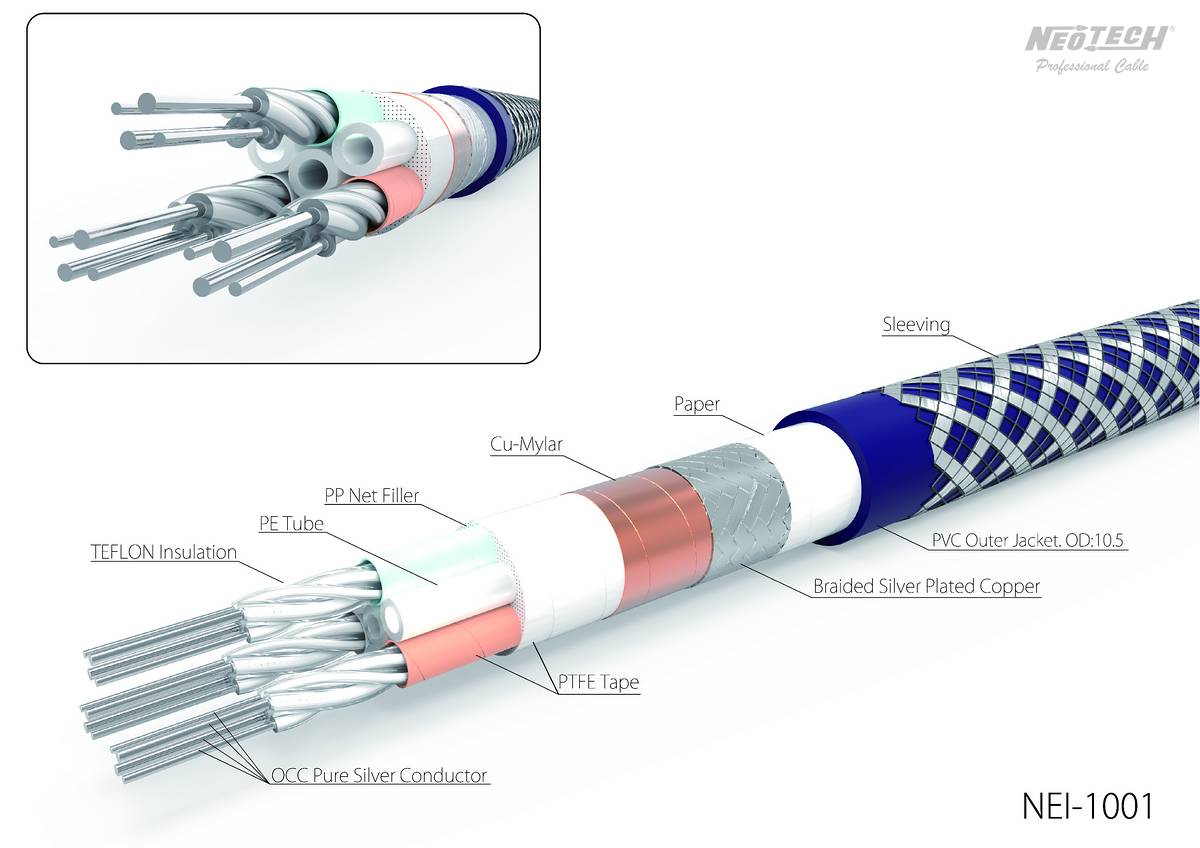
2. Is there any advantage in spacing out the three wires by empty teflon tubes (like in the diagram below, where Neotech used empty teflon tubes to maintain a constant distance between the signal conductors)? Or is there any theoretical difference including the inaudible range?

3. In the diagram below, each signal conductor is made up of four individually insulated strands twisted together. I believe this is something similar to a Litz wire? Is there any advantage to this over a single conductor for +ve, -ve and ground respectively?

I'm asking because I have rolls of unused teflon tubes people threw out and therefore I can create any interesting design which is scientifically sound without extra cost. I just don't have briaded shielding at hand.

Thank you!


NEI-1001.jpg
 
Last edited:

unpluggged

Senior Member
Joined
Jan 5, 2023
Messages
469
Likes
694
Should I twist all three wires in the same direction?
:oops:

3-pin XLR uses a shielded twisted pair. There are only two wires as such, plus an outer shield that connects to pin 1. Why not get a specifically manufactured microphone cable for the purpose? They are very affordable.
 

Blumlein 88

Grand Contributor
Forum Donor
Joined
Feb 23, 2016
Messages
20,694
Likes
37,423


Non-technical answer. I've seen some cheapo XLR which has a twisted pair and then spirals a third wire connected to ground around the outside of those. A cheapo shield. Those have sometimes picked up noise. Those also have a low and uneven twist rate in my experience. I've made them myself by braiding the three wires like braiding pigtails without a shield. Never a problem with those when I've made them this way. While most XLR cable is a shielded twisted pair for audio, things like ethernet are unshielded twisted pairs (UTP).
 
OP
J

JensenW

Member
Joined
Jan 3, 2022
Messages
48
Likes
10
:oops:

3-pin XLR uses a shielded twisted pair. There are only two wires as such, plus an outer shield that connects to pin 1. Why not get a specifically manufactured microphone cable for the purpose? They are very affordable.
Gotham has a GAC-3 cable which has theee conductors and a shield, the so-called Neumann cable. I wonder if a dedicated third conductor connecting the two ground pins of the XLR makes any scientific difference.


The Neotech NEI-1001 (the photo attached in the original post) is also a three-conductor cable, and it also has empty tubes to space out the distance between the conductors as well. It is super expensive though and I don't think it is worth spending that sum on a cable that won't sound different.

Since I have a surplus of bare wires and teflon tubes, I can make three-conductor wires and create distance between conductors, or twist them or braid them if any of these ideas has certain advantages, even if inaudible. Just for the fun and sake of making it.
 
OP
J

JensenW

Member
Joined
Jan 3, 2022
Messages
48
Likes
10
I've made them myself by braiding the three wires like braiding pigtails without a shield. Never a problem with those when I've made them this way.
Have you tried comparing braiding them vs twisting them all in the same direction, i.e grabbing all three wires in the hand and simply twist them right away?
 

Blumlein 88

Grand Contributor
Forum Donor
Joined
Feb 23, 2016
Messages
20,694
Likes
37,423
Have you tried comparing braiding them vs twisting them all in the same direction, i.e grabbing all three wires in the hand and simply twist them right away?
No, I have not. The main idea is to swap position of the two signal carrying wires regularly and equally. Just doing a thought experiment, braiding would do that better than a 3 wire twist. If you used two ground wires you could have the signal carrying wires in a more symmetrical twist. Basically a star quad arrangement without an outer shield. However, just taking three wires and twisting them is going to work at audio frequencies, and might be better as it will be easier to keep a tight twist.
 

Speedskater

Major Contributor
Joined
Mar 5, 2016
Messages
1,636
Likes
1,357
Location
Cleveland, Ohio USA
In a balanced interconnect system, there are two signal conductors and a shield. There is no ground wire!
In a balanced microphone system, there are two signal conductors and a shield. The shield is often part of the phantom supply and may be at the phantom supply common potential.
It is important for the two signal conductors to have symmetrical placement with respect to the shield.
A third central conductor may cause the two signal conductors to have unsymmetrical placement. This will increase Shield Current Induced Noise current.
 

fpitas

Master Contributor
Forum Donor
Joined
Jul 7, 2022
Messages
9,885
Likes
14,201
Location
Northern Virginia, USA
In a balanced interconnect system, there are two signal conductors and a shield. There is no ground wire!
In a balanced microphone system, there are two signal conductors and a shield. The shield is often part of the phantom supply and may be at the phantom supply common potential.
It is important for the two signal conductors to have symmetrical placement with respect to the shield.
A third central conductor may cause the two signal conductors to have unsymmetrical placement. This will increase Shield Current Induced Noise current.
Yes. This isn't a, "one is good, two is better, three is even better" scenario.
 

Blumlein 88

Grand Contributor
Forum Donor
Joined
Feb 23, 2016
Messages
20,694
Likes
37,423
In a balanced interconnect system, there are two signal conductors and a shield. There is no ground wire!
In a balanced microphone system, there are two signal conductors and a shield. The shield is often part of the phantom supply and may be at the phantom supply common potential.
It is important for the two signal conductors to have symmetrical placement with respect to the shield.
A third central conductor may cause the two signal conductors to have unsymmetrical placement. This will increase Shield Current Induced Noise current.
I'm not suggesting otherwise. Best is twisted pair or star-quad and shielding. However, a double twisted pair with one pair being grounded or a 3 wire braid will place the pin 2 and 3 symmetrically about each other and work fine. I wouldn't want it unshielded for a 100 foot microphone run, but for 5 meters or less at line level it will work fine. The OP wants to make his own cables using on-hand scrap wire which isn't shielded. Grabbing three wires and doing a simple twist won't be symmetrical while a 3 wire braid will be. Grabbing two wires for a tight twist and then spiraling the ground wire around it would work too.

Of course unless I just wanted to use up the wire, I'd buy ready made cable from World's Best or somewhere like Redco and save myself the trouble.
 

Blumlein 88

Grand Contributor
Forum Donor
Joined
Feb 23, 2016
Messages
20,694
Likes
37,423
There is no 'ground wire' in an XLR balanced interconnect system. And a wire would make a awful shield.
No kidding. So what does that pin 1 in an xlr connector do? It is neutral if you insist. It serves as drain for phantom power on pins 2 and 3. And the shield is usually connected to chassis ground. Ground wire doesn't carry signal. And I myself have said wire is a poor shield, but it will serve all other functions and serve as a poor, but for short runs adequate shield.
 
OP
J

JensenW

Member
Joined
Jan 3, 2022
Messages
48
Likes
10
Thanks for all the kind contributions and advice!
So what I get is:
1. At its very best (perfectly twisted or braided), a 3-conductor XLR has no advantage over a twisted pair+ shield.
2. If I must make a 3-wire cable without shield, then braiding is better than twisting as it is easier to keep the twist uniform and symmetrical.

It appears that the best thing to do with my scrap wires, is to spend a few dollars on a short length of braided shield tube and nylon outer cover tube, which could be had quite cheaply, and put my twisted pair into the shield tube, and then the whole thing into the nylon tube, and this should theoretically outperform a hand-twisted 3-conductor cable without shield.
 

Speedskater

Major Contributor
Joined
Mar 5, 2016
Messages
1,636
Likes
1,357
Location
Cleveland, Ohio USA
No kidding. So what does that pin 1 in an xlr connector do? It is neutral if you insist. It serves as drain for phantom power on pins 2 and 3. And the shield is usually connected to chassis ground. Ground wire doesn't carry signal. And I myself have said wire is a poor shield, but it will serve all other functions and serve as a poor, but for short runs adequate shield.
Just because there is continuity between two functions, does not make them the same function.

XLR pin 1 is connected to the chassis. The circuit common and DC supply common are also connected to the chassis.

a] in an XLR balanced interconnect system, the shield is not always connected at the receive end. In fact some experts recommend not connecting the shield at the receive end (and using a hybrid connection).

b] In a microphone system, with phantom power, +DC is on pins 2 & 3, with -DC on pin 1. Not connected to 'ground' but has continuity to 'ground".
 

Justin Zazzi

Member
Joined
Sep 12, 2020
Messages
32
Likes
32
Location
Tempe, AZ
Another option to make a very consistent twist is use a cordless drill.


AnalogSteph

Major Contributor
Joined
Nov 6, 2018
Messages
3,373
Likes
3,318
Location
.de
Cable construction will influence both function and parasitics.

Twist hot and cold wires tightly, and cancellation will be effective to higher frequencies, while parasitic inductance lowers and parasitic capacitance increases. (BTW, this also means that characteristic impedance √(L/C) goes down.)
If you wind a third wire across the whole shebang as a shield it'll basically work but but highly inductive, as expected for a wirewound resistor or a coil. This is why a braid is much preferred here. The size ratio of inner conductors and shield is going to influence parasitic common-mode capacitance, see cylindrical capacitor.

BTW, a new set of challenges arises in a phantom powered microphone application. As now there is a DC voltage between both conductors and shield, any change in the absolute difference between "hot to shield" and "cold to shield" capacitance will be made audible. I have two 10m XLR cables floating around that I don't quite know what to do with because the cable stock is badly microphonic as soon as phantom power is turned on, so clearly the internal conductors must be loose and moving around. They are solidly built otherwise, so it's a bit of a bummer.
 
OP
J

JensenW

Member
Joined
Jan 3, 2022
Messages
48
Likes
10
I was wondering, if I braid three conductors and connect each of them to pins 1,2,3 on both sides, would the third wire serve any shielding function?

A friend also mentioned using oversized teflon tubes to reduce capacitance. However, I guess it is even harder to create a symmetrical twist if the wire is loose inside the tube.
 
Last edited:

3125b

Major Contributor
Joined
May 18, 2020
Messages
1,357
Likes
2,216
Location
Germany
How about you make some different ones and send them to Amir to measure?
Guess I could make one out of a power cable, see how well that works compared to a proper microphone cable - without looking further into it I'd expect a small measureable but not audible difference (when not right next to a severe EMI source).

I measured interference from a power supply with balanced and unbalanced connections once, can't find my post, but with a cheap microphone cable (two cnductor with shield) the cable needed to be wound tightly in many turns around a loaded laptop power supply to measure any signal degradation, and even then SINAD was still well over 100dB, so with any sort of reasonable cable geometry balanced connections are highly resistant to EMI.
 

Speedskater

Major Contributor
Joined
Mar 5, 2016
Messages
1,636
Likes
1,357
Location
Cleveland, Ohio USA
I was wondering, if I braid three conductors and connect each of them to pins 1,2,3 on both sides, would the third wire serve any shielding function?
Just the opposite! It's not a shield, and would mess-up the symmetry of the TWO central conductors.
Just get a Shielded Twisted Pair (STP) bulk cable from a major industrial manufacture. You can't DIY anything even close.
 
Top Bottom