• WANTED: Happy members who like to discuss audio and other topics related to our interest. Desire to learn and share knowledge of science required. There are many reviews of audio hardware and expert members to help answer your questions. Click here to have your audio equipment measured for free!

DIY inspired Buchardt S400 – Crossover design

Most manufacturers test their drivers on an IEC baffle which is standardized for frequency response, but the distance of the measurement can vary or not be stated. The scales used can make a big difference in how something looks. A compressed vertical scale will make the driver look flatter, the same data viewed in Vituix will look different because the scale is more equal between horizontal and vertical.

For experimenting and for anyone not well versed in passive crossover design or someone who already has a large stock of passive parts an active crossover is considerably easier to get right, and easily changed if it turns out you made a mistake along the way.
Will second the above...

For both reasons (baffle step and flexibility), will second that an active crossover is the way to go. Even if you plan to make the design passive eventually, you will likely save the cost of a minidsp 2x4 in passive parts. If your plan is to go passive in the end, you simply need to consider designing with that in mind (keep it simple, avoid high order filters, no delays, and padding the tweeter. :)
 
Last edited:
This is an excellent point. Unless conditions are stated, it is difficult to know how comparable drivers specs are. As Xmax is a key one for sims, not surprised that all drivers may not yet based on Klippel metrics. If a driver was developed prior to Klippel are they going to go back remeasure and restate Xmax to (a likely lower value)? Probably not.
All serious driver manufacturers have their own or access to a Klippel system for driver testing and that has been the case for a long time for most.
They know that the linear x-max they quote based on physical distances does not relate to the linear performance of the driver. They still quote it because it often looks good on the spec sheet and is not actually a lie. B&C quote XVar which is where any level of performance has dropped to 50%. Sometimes the driver can actually have distortion below 10% beyond the linear x-max excursion range but usually the manufacturer is happy to tell you about that :)

If they have a Klippel, it should be part of the stated conditions. For the OP‘s SB woofer, it is not. Should not have to chase manufacturers for conditions. They could state more than just a mechanical distance, but as you indicate, they often choose not to do. We should not have to acquire and measure drivers to accurately compare them either.

Anyway, getting off topic and may be a good topic for new DIY thread. ;)
 
Last edited:
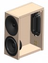
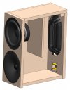
While I’m making few test with the Umik 1 on my current loadspeeker, here is a first draft of the project (Attached 3D pdf file – To open click on yellow option button on top right, then « Approve the document… » - Right click to zoom / Left click to move).
Everything is not ajusted yet as I need to be sure of the drivers dimensions fisrt (not ordered yet).

I’m planning to make the box using 16mm MDF. Bracing ? Due to the size of the box, not sure if it’s necessary…
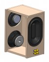
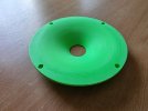
The two drivers housing are exactly the same size so that I can revers beetween tweeter on top or on the bottom. Waveguide is a derivative version of the 6’’ Augerpro waveguide.
Clearly I d’on’t believe (May be I’m wrong) in time alignement things thanks to the tilted box. For me it’s more a matter of aesthetics and I really like such design.

I’m questioning myself on two points:
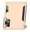
-Is there any optimal position for the passive radiator? (the farthest or nearest from the woofer, centrered on the back plate surface?)
-Should I make the back plate removable so that I can adjust the passive radiator position? Easy acces to a potential passive crossover ?
 

Attachments

  • RLB01.PDF
    584.9 KB · Views: 140
Last edited:
... Klippel ... XVar ...
I reiterate myself. The problem is not the distortion in bass itself. Every bass instrument necessarily generates vast harmonic content. Otherwise it wouldn't be heard, as the hearing is quite insensitive, and only marginally discerning down below. So, an acoustic/upright bass may show 1000% (one 000) percent of second harmonics, my e-bass shows at least 200%.

It is the intermodulation that counts, especially with a two way! The suspension's non-linearity is a non issue regarding IM. So, the Klippel is a bit misleading here.

BL variation sets the crucial limitation for most drivers.

Second to that many drivers have resonant surrounds. The surround takes a bigger part in the radiation of sound. High excursion modulates the radiation of the surround. Due to that IM may reach up to 30% easily, while distortion in bass may be kept as low as 3% or so. E/g: an XBL^2 driver I measured, another very high class JBL driver too ...

Regarding IM please acknowledge, that Doppler can be heard! There is some rumour that the phase alignment of "frequency modulation" (Doppler) discriminates it against "amplitude modulation" (motor non-linear), which makes it by far less audible. True - tested it myself with headphones! But - that special phase alignment of the side-bands is *not* maintained with speakers. The listening room with all its reflections finally shifts phase chaotically. No escape here.

To have a clean speaker, please just ignore IM, as all do. Or limit the Doppler distortion to something around 1%, which renders a high excursion motor useless for a 2-way. As a rule of thumb one might derive from Klippel's "Doppler limit" an excursion limit of +/-3mm.
 
Last edited:
Little update on the design and first 3D printing of a prototype wave guide (FDM - color is uggly for a wave guide but it's just a proto).
I finally found a second hand MiniDSP Nanodigi to use with my FDA amp so thoses speakers will be active for the beginning a least.
 

Attachments

  • Assemblage1.JPG
    Assemblage1.JPG
    122.4 KB · Views: 192
  • Assemblage2.JPG
    Assemblage2.JPG
    142.2 KB · Views: 183
  • Assemblage3.JPG
    Assemblage3.JPG
    115.2 KB · Views: 185
  • 20220421_174840.jpg
    20220421_174840.jpg
    357.8 KB · Views: 193
Little update on the design ... found a second hand MiniDSP Nanodigi to use ...
Great find, it will ease Your life a lot! So, You may want to tune the speaker even deeper, and adjust the bass level by equalisation to Your particular need in Your room.
A little bit of cross-bracing the enclosure internally could help. Not the least as You have all the rest in very good shape me thinks.

You know that Buchardt had some serious problems with the drone/passive speaker? Resonance. Maybe it would be beneficial to "shadow" the drone by a wall in the middle of the enclosure from the right to the left wall. Of course leaving, say at top and bottom, some openings similar to the drivers surface area? That wall would double-serve as a cross-bracing perfectly.

Btw. the slanted design is for the looks only, right? Acoustically its effect is quite close to nothing ;-)
(If people need it, the x-over is failed, bad phase shifts etc.)
 
Last edited:
You know that Buchardt had some serious problems with the drone/passive speaker?
@fineMen , thanks for the informations / remarks.
I was not aware that Buschardt had some resonance issues. It’s difficult to know if it’s due to lag of brassing or a lag of sonic Barrier in the cabinet.

May be the Directiva R1 team can help me on that topic. @Rick Sykora did you test the speakers without the sonic barrier ahead of the passive radiator and if so, did you encouter such resonnance phoenomenon ?

Btw. the slanted design is for the looks only, right?
Yes it’s only for the look, as mentionned in a previous post, I don’t believe in those marketing arguments…
 
@fineMen , thanks for the informations / remarks.
I was not aware that Buschardt had some resonance issues. It’s difficult to know if it’s due to lag of brassing or a lag of sonic Barrier in the cabinet.

May be the Directiva R1 team can help me on that topic. @Rick Sykora did you test the speakers without the sonic barrier ahead of the passive radiator and if so, did you encouter such resonnance phoenomenon ?


Yes it’s only for the look, as mentionned in a previous post, I don’t believe in those marketing arguments…

Yes, I played with various damping materials and did not find any significant benefit to placing some of the more dense ones behind the PR.

However, did not have a brace that would avoid more direct interaction between the woofer and the passive radiator. If your design can accommodate, may prove to be beneficial. The worst resonance we encountered was when I mounted the Purifi PRs on the side of a truncated pyramid cabinet. I tried to remediate but eventually abandoned that cabinet design.

Agree that the slanted cabinet is mainly rendered pointless if you can implement a delay in the active crossover. Directiva r1 uses the delay to comp for more than just the driver offsets. It can be used to refine the phase matching between the drivers as you design the crossover. It gives you way more flexibility than more fixed mechanical compensation,
 
If adding a direct barrier to the passive radiator has a positive impact, perhaps it would also be good to reverse the position of the Woofer and the tweeter so that the wave from the woofer is as far away from the passive radiator as possible.
Is that what you recommend ?
 

Attachments

  • Assemblage2.JPG
    Assemblage2.JPG
    1.6 MB · Views: 132
  • Assemblage1.JPG
    Assemblage1.JPG
    138.5 KB · Views: 133
Last edited:
If adding a direct barrier to the passive radiator has a positive impact, perhaps it would also be good to reverse the position of the Woofer and the tweeter so that the wave from the woofer is as far away from the passive radiator as possible.
Is that what you recommend ?
The resonance @518Hz: https://www.audiosciencereview.com/forum/index.php?threads/buchardt-s400-speaker-review.12844/

Anyway, if it works, who knows? Only to kick You into desperation, the asymmetry could make the drone wobble... ;-)

I do "rapid prototyping" for long now, and all my speakers remain in that state. Why? Because the problems weren't that severe in the end ;-)

I thought of a wall, which keeps both, the top and the bottom free for airflow, giving a bit of an asymmetry, but not too much.

The "barrier" doesn't block sound, but it would just lengthen the path, by that lowering a potential resonance, and aside bringing the dampening to more effect.

A rough and easy prototype, rectangular, mono, what do You think? You would be one of the few who really optimise their works.
 
Yes it’s only for the look, as mentionned in a previous post, I don’t believe in those marketing arguments…
You might only be choosing it for the look but it most certainly has an effect on the response that you will get. Tilting a baffle will change the response that you hear as on or off axis and will change the phase relationship between the drivers. It is something to consider and simulate if you can in Vituix with the tilt function.
 
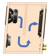
For fun, here is an airflow simulation of the cabinet with two different positions for the central brassing.
I'm not sure that such simulation and my input parameters are relevant since the simulation is with a constant laminar airflow and with an open inlet and outlet (may be better in BR solution)...
However this gives an idea of the flow of the flux. I would say that the solution on the right proposed by @fineMen gives a more balanced distribution of the flow on the passive radiator.
 
I’m using the FloExpress module in Solidworks. It’s very basic compared to some other CFD software.
 
Here’s another Buchardt-inspired DIY design:

 
I’m using the FloExpress module in Solidworks. It’s very basic compared to some other CFD software.
Is there some free software capable of some air flow simulation that could be used in enclosure, port design for potential DIY loudspeaker builders? I understand Solidworks is professional soft and rather $$$. Anything in CFD soft like the Vituix. I like the video you presented.
Going back to tilted baffles, sometimes it helps to have the baffle tilted so the acoustic centers of the drivers align, sometimes it doesn't. For drivers like the SB17NBAC which need additional compensation to get rid off cone breakups, LR4 based passive crossover would the most useful. In loudspeaker I built with 17NBAC-4, having the tweeter on 10deg sloped baffle, or tweeter in the waveguide, or on stepped baffle the way Trolls does it, simplified things, however it usually depends on drivers used. Some are easier to 'hammer' into right transfer function and align their phases than others. Took me a while before I was satisfied with what I was hearing, even though the CAD simulations differed from each other by dB or less here and there. Getting the saxophone, trumpet, drums to sound good is sort of a obsession, since their the overtones sit right in crossover area.
 
There are a couple of plugins for FreeCAD that give integration with the OpenFOAM CFD solver. How complete it is I don't know - not my field.
 
I think it is an interesting help however my simulation is full of approximation and does not consider an essential parameter, damping. In addition, the sound is composed of waves and not a continuous laminar flow of air so I'm not sure of the degree of effectiveness of this type of simulation.
There is plenty of free basic CFD software however I never tried anything else than the Flow module I have on my work computer.

Little update on my project:
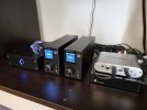
I received the MiniDSP Nanodigi that I bought second hand and using my SMSL AD18 with the SPDIF coax input (I read the test and comments of this “very bad” amp on this forum and was not conviced at all by test protocol (inputs/outpouts choice) – Personally I love this budget amp). AD18 are powered by an SMSP300RS power supply that I assembled last winter.
I tested the setup on my loudspeakers where I used active above passive filter just to understand how it work.
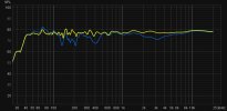
Still have work to do but EQ looks easy…(Blue before/yellow after).

And I just received the speakers. Cabinets will be CNC routed in the upcoming weeks.
 

Attachments

  • 20220512_222035.jpg
    20220512_222035.jpg
    362.6 KB · Views: 116
  • 20220523_143411.jpg
    20220523_143411.jpg
    181.9 KB · Views: 128
  • WhatsApp Image 2022-05-13 at 10.10.49.jpeg
    WhatsApp Image 2022-05-13 at 10.10.49.jpeg
    95.5 KB · Views: 133
  • 20220520_152735.jpg
    20220520_152735.jpg
    211.8 KB · Views: 125
Last edited:
I think it is an interesting help however my simulation is full of approximation and does not consider an essential parameter, damping. In addition, the sound is composed of waves and not a continuous laminar flow of air so I'm not sure of the degree of effectiveness of this type of simulation.
There is plenty of free basic CFD software however I never tried anything else than the Flow module I have on my work computer.
There is discussion online about setting boundary conditions for different sorts of oscillatory flow in OpenFOAM, so it's not just continuous flow. I don't know if anyone has tried applying it to ports in speakers, or whether that takes it into conditions it can't model. I suspect it will take some skill and model verification to get a meaningful result in any case.
 
Back
Top Bottom