• WANTED: Happy members who like to discuss audio and other topics related to our interest. Desire to learn and share knowledge of science required. There are many reviews of audio hardware and expert members to help answer your questions. Click here to have your audio equipment measured for free!

DIY CCS-loaded 45 Tube Headphone Amp

L0rdGwyn

Active Member
Forum Donor
Joined
Jan 15, 2018
Messages
295
Likes
676
Hey ASR - wanted to share a project I just completed. I am a "tube guy", back in January I decided I was going to start building my own gear. That began with a 6A5G SET 3WPC speaker amplifier, which turned out quite well I think. 3 WATTS, WUT?! My speakers are 6ohm 98dB/W in a small room, I am living a happy flea-watt life.

But what I am sharing here is my second effort, a dedicated headphone amp. I know tubes aren't exactly this forum's cup of tea, I think this build will be a bit more palatable, measurements-wise, than my 6A5G amp (which uses an unreguated CLCLC PS and some super vintage tubes that I believe have some degree of heater-to-cathode leakage). It features a cascode MOSFET CCS-loaded 6J5 input stage, followed by a cascode MOSFET CCS-loaded 45 parafeed output stage. Mains transformer is a custom job by Sowter to my spec, OPT are Sowter 8983. Filament regulators are Rod Coleman's, coupling and parafeed caps are Rike Audio S-Cap 2 (paper, poly, aluminum, oil). Power supply is a single rail CLCRC.

DSCF5611.jpgDSCF5615-2.jpg11224562.jpg

Here is the schematic, although it is not comprehensive. Parafeed capacitance was determined experimentally by taking FR sweeps of various capacitances (courtesy of cheap Solen caps), along with subjective listening impressions. Ultimately decided on 6.6uF made up of two 3.3uF in parallel.

45 Parafeed Schematic.png45 Parafeed PS.png

Bias points:

6J5 B+: 380V
6J5 plate to cathode: 200V
6J5 cathode: 6.2V
6J5 plate current: 8.5mA

45 B+: 398V
45 plate to cathode: 206V
45 cathode: 35.5V
45 plate current: 35mA

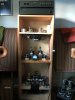
Here are some shots of the interior. Bottom plate is perforated aluminum sheet for ventilation.

DSCF5602.jpgDSCF5603.jpgDSCF5605.jpgDSCF5609.jpg

Here is a FFT of the left channel at 350mV into 300ohms. I've traced the residual 60Hz noise to capacitive coupling within the mains transformer, reaching the signal output via the filament regulator. It's a bit worse on the right channel. Regardless, it is inaudible to my ears, so I'm letting it go.

11230661.png

And the frequency response.

11230659.png

Thanks for checking it out!
 
Last edited:

LTig

Master Contributor
Forum Donor
Joined
Feb 27, 2019
Messages
5,814
Likes
9,528
Location
Europe
Did you measure the output impedance over frequency?
 
OP
L0rdGwyn

L0rdGwyn

Active Member
Forum Donor
Joined
Jan 15, 2018
Messages
295
Likes
676
Did you measure the output impedance over frequency?

No, I did not. After the effort that went into this build, I have been enjoying the spoils, so just some simple measurements were taken. I can put it on the "to-do" list.
 
Last edited:

mhardy6647

Grand Contributor
Joined
Dec 12, 2019
Messages
11,372
Likes
24,579
Nice.
6J5 driving a 45. Absolutely classic.
Constant current source is a nice touch. :)
It is a beautiful amplifier, too!

Hard to go wrong with the 45 -- heck of an audio power triode if the output power is adequate (which, of course,for a headphone amp, it is!).
I can't quite get away with 45s here, so we 'settle' for 2A3s driving the Frankenaltecs :)
 
OP
L0rdGwyn

L0rdGwyn

Active Member
Forum Donor
Joined
Jan 15, 2018
Messages
295
Likes
676
Nice.
6J5 driving a 45. Absolutely classic.
Constant current source is a nice touch. :)
It is a beautiful amplifier, too!

Hard to go wrong with the 45 -- heck of an audio power triode if the output power is adequate (which, of course,for a headphone amp, it is!).
I can't quite get away with 45s here, so we 'settle' for 2A3s driving the Frankenaltecs :)

Thanks for the kind words :) I very nearly used a hot bias on the 45 and threw on some speaker binding posts, but decided against it, ultimately. Would've gotten 2W into 8ohms, but it would have cost me some chassis real estate, a somewhat small form factor was a priority since it lives on my desk. Had to cram a lot in there!
 

anystereo

New Member
Joined
Nov 17, 2020
Messages
1
Likes
2
Hi,
Nice job. I have a very similar amp. Mine is a based on Gordon Rankin's Bugle, but its parafeed and I have rod coleman's filament supplies. I'd like to compare notes with you. There are a few things that you've done that I haven't tried. My cathode cap is only 22 uf yours is 200! Also your coupling cap is also much bigger, mine is 0.047uf = 1/2xPIxFxR. F = low-end frequency boundary, R = the grid resistor = 470K. I have not calculated the parafeed cap but have been using 3.3 as recommended by Paul Joppa. I used the calcs for both the cathode and the coupling that gordon shows in his article. I use the amp for both my speakers (lowther PM5A's) and my headphones (Audeze LCD-X) both are working off the 16 OPT secondary. All my iron is from Magnequest. It's a really great setup, the 45's are so transpart that what I hear most is the driver stage I think. And I am always playing with the circuits and am looking enviously at your driver stage, the 6J5's might be the next best thing. Any recommendations?
 

Attachments

  • IMG-6837-1.jpg
    IMG-6837-1.jpg
    326.5 KB · Views: 224
OP
L0rdGwyn

L0rdGwyn

Active Member
Forum Donor
Joined
Jan 15, 2018
Messages
295
Likes
676
Hi!

Your values sound fine, I have since made changes to that design. I set the -3dB frequency for the coupling cap to 1Hz to avoid any LF attenuation, C = 1/(1Hz * 2pi * 470K) = 0.34uF. More won't hurt anything, but 0.047uF should work just fine with a cutoff at 7Hz.

The cathode bypass cap definitely does not need to be 220uF for the 45, I have since reduced the value and I am using a film capacitor in that position, your 22uF should be good. Are you using a choke or a FET CCS on the 45? If using a choke, the parafeed cap value can be calculated, there is no surefire way to calculate the value if using a FET CCS active load, best to do it experimentally. What are you using as your driver right now? I do like the 6J5, it is a nice driver tube.
 
OP
L0rdGwyn

L0rdGwyn

Active Member
Forum Donor
Joined
Jan 15, 2018
Messages
295
Likes
676
I rebuilt and rebiased this amplifier for speakers, meaning the full 1.5W of the 45 is now available :cool: watch out world.

I am running it in my bedroom with a pair of Klipsch KG 1, 90dB/W sensitive, not going to bring the house down but loud enough for my space.

DSCF6316-min.jpg DSCF6311-min.jpg DSCF6315-min.jpg DSCF6328-min.jpg DSCF6310-min.jpg DSCF6335-min.jpg
 

pozz

Слава Україні
Forum Donor
Editor
Joined
May 21, 2019
Messages
4,036
Likes
6,827

Maki

Active Member
Joined
Oct 24, 2018
Messages
252
Likes
478
Amazing build. What's the chassis, did you make it yourself?
 
OP
L0rdGwyn

L0rdGwyn

Active Member
Forum Donor
Joined
Jan 15, 2018
Messages
295
Likes
676
Amazing build. What's the chassis, did you make it yourself?

Thanks! The chassis design / layout was done in AutoCAD software, the machining was done by a small company called Landfall Systems who I work with for all of my DIY builds.
 

Germano Puhl

New Member
Joined
Sep 6, 2022
Messages
1
Likes
0
Hi, is it possible to use a 2a3 on it? what changes would i need to make? Hugs from Brazil
 
OP
L0rdGwyn

L0rdGwyn

Active Member
Forum Donor
Joined
Jan 15, 2018
Messages
295
Likes
676
Hi, is it possible to use a 2a3 on it? what changes would i need to make? Hugs from Brazil

Yes, you could build something similar for 2A3. You would need to adjust the filament supply to handle the higher current of the 2A3 (2.5A vs. 1.5A of the 45). You would also want to use a different output transformer, Sowter makes a 2.5K parafeed transformer for the 2A3, the 8995.

I no longer have this amplifier though, I took it apart, too many amps. Still have the transformers, I may use the custom mains I had made for a direct-coupled 45 amplifier, likely for headphones.
 
Top Bottom