Dave Zan
Active Member
Hi Dave, these impressive noise levels have been pretty common now for years in MEMS mics.
Thanks for the links, the noise is better than the ones I remember and indeed impressive.
...you must appreciate about a MEMS data sheet is that it is completely spec'd. Few conventional mics are....
1) https://www.invensense.com/download-pdf/ics-52000-data-sheet/
2) https://www.invensense.com/products/analog/ics-40618/
Better spec'ed in some areas, a bit short on details in others, no polars?
Should be close to omni if it can be mounted in a sufficiently tiny probe so probably not an issue..
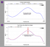
The TDK in your second link is low noise but much worse frequency response compared to the AD devices plots you showed.
Practically +-10 dB from 20 Hz to 20 kHz.
I know this can be included in a calibration file but it doesn't fill me with enthusiasm.
Spec'd for tolerance at 1 kHz but no frequency band tolerance?
Probably very repeatable but it would be nice to have a spec.
I do think phase match will be a problem for an array version of this project but I am really happy to have learned about the current state of the art in MEMS microphones.
Best wishes
David
Last edited:
")