• WANTED: Happy members who like to discuss audio and other topics related to our interest. Desire to learn and share knowledge of science required. There are many reviews of audio hardware and expert members to help answer your questions. Click here to have your audio equipment measured for free!

Dirac-like impulse response corrections in rePhase?

Naughtius

Member
Joined
Mar 4, 2022
Messages
56
Likes
70
I've been playing around with a Dirac live trial - being used to using simple parametric filters only - and it really seems to clean things up in the time domain. Image heavy:

Raw Im.jpg
Dirac Im.jpg

Raw Step.jpg
Dirac Step.jpg


Raw Wavelet.jpg
Dirac Wavelet.jpg

Bass Raw.jpg
Bass Dirac.jpg


Does anyone here know what they're doing under water? And how one would go about implementing similar 'mixed phase' filters manually, for example using REW and rePhase? I'd love to hear!
- David
 

Attachments

  • Karl Raw vs Dirac.zip
    2.5 MB · Views: 101
Last edited:

ernestcarl

Major Contributor
Joined
Sep 4, 2019
Messages
3,113
Likes
2,330
Location
Canada
I've been playing around with a Dirac live trial - being used to using simple parametric filters only - and it really seems to clean things up in the time domain. Image heavy:

View attachment 191905View attachment 191906
View attachment 191907View attachment 191908

View attachment 191949View attachment 191951
View attachment 191952View attachment 191954

Does anyone here know what they're doing under water? And how one would go about implementing similar 'mixed phase' filters manually, for example using REW and rePhase? I'd love to hear!
- David

I've created a simple MP FIR correction based on the Dirac corrected measurement you provided. Try to load the IR correction using a convolver and see if you get similar results with the "rePhase copy".

1647137928691.png


1647137932878.png


1647137936719.png


1647137940981.png


1647137946922.gif


1647137972999.png


1647137977073.png


*do note the sample rate used; I also omitted to add a boost around 25 Hz


-------


Magnitude and Phase Comparison of simple rePhase "copy" to the Actual Inverted Version
A (Dirac) / B (Raw)

1647149158772.png


1647149165011.png
 

Attachments

  • Karl rePhase MP FIR correction test.zip
    2.9 MB · Views: 75
Last edited:

ernestcarl

Major Contributor
Joined
Sep 4, 2019
Messages
3,113
Likes
2,330
Location
Canada
One more thing I forgot which you need to do:

1647139729310.png


This is to ensure you have enough headroom and won't clip with a 0 dBFS signal.
 

Holmz

Major Contributor
Joined
Oct 3, 2021
Messages
2,020
Likes
1,242
Location
Australia
@Naughtius are you doing the measurement in a room?
Or outside away from reflections?
(I think that the 6msec echo sort of suggest that they are in a room about 3 feet from the back wall.)

Does anyone do the work on the speakers outside and then apply that Dirac/RePhase to the speaker?
( And maybe some room mode stuff for the <400Hz)?
 

ernestcarl

Major Contributor
Joined
Sep 4, 2019
Messages
3,113
Likes
2,330
Location
Canada
Does anyone do the work on the speakers outside and then apply that Dirac/RePhase to the speaker?

I'd probably do that and be even more thorough if I were correcting a DIY speaker. Right now, I personally already use multiple references including the results from MMM, multiple spatially averaged measurements, and/or quasi-anechoic on- and off-axis curves for stuff above 1 kHz. Theoretically, a single point may be enough to work well esp. if the speaker already measures very good, room acoustics is good, and if one is mindful of not over-correcting. Hmmmn... but, I'd still rather not want to rely too much on a single reference.
 
OP
N

Naughtius

Member
Joined
Mar 4, 2022
Messages
56
Likes
70
I've created a simple MP FIR correction based on the Dirac corrected measurement you provided. Try to load the IR correction using a convolver and see if you get similar results with the "rePhase copy".

View attachment 192019

View attachment 192020

View attachment 192021

View attachment 192022

View attachment 192023

View attachment 192024

View attachment 192025

*do note the sample rate used; I also omitted to add a boost around 25 Hz


-------


Magnitude and Phase Comparison of simple rePhase "copy" to the Actual Inverted Version
A (Dirac) / B (Raw)

View attachment 192048


View attachment 192049

Thanks for diving in like this! Your copy works exactly as advertised:
EC Comp.jpg


R.jpg

D.jpg
E.jpg


It'd love to learn how to do similar corrections without Dirac, would you be able to provide some guidance on that?

(Happy to be able to keep going when the Dirac trial ends.) ;)
 
OP
N

Naughtius

Member
Joined
Mar 4, 2022
Messages
56
Likes
70
@Naughtius are you doing the measurement in a room?
Or outside away from reflections?
(I think that the 6msec echo sort of suggest that they are in a room about 3 feet from the back wall.)

Does anyone do the work on the speakers outside and then apply that Dirac/RePhase to the speaker?
( And maybe some room mode stuff for the <400Hz)?
I'm inside! Good call, 3 feet 2 inches.

I do have two 12" mattresses behind the speakers until I get some proper treatment - looks like it doesn't help too much
 
OP
N

Naughtius

Member
Joined
Mar 4, 2022
Messages
56
Likes
70
I think DRC will do the trick.
That was a deep dive, I ended up using DRCDesigner with measurements from REW, but the results are great!

Here's the results from no EQ to the DRC filters:
DRC Step.jpg

1.jpg
2.jpg

LR1.jpg
LRA1.jpg

LR.jpg
LRA.jpg


I do have absolutely no clue what is happening under water, and am very curious to learn how these filters correct the time domain. Would there be a more DIY approach to see / play with these effects in for example RePhase?

Thanks a lot for the DRC suggestion, great stuff!
 

voodooless

Grand Contributor
Forum Donor
Joined
Jun 16, 2020
Messages
10,402
Likes
18,357
Location
Netherlands
There’s a GUI for it as well: https://github.com/aljordan/DRCDesignerWindows

Want to know what it does? Here it is a brief summary of what DRC does:

  1. Initial windowing and normalization of the input impulse response.
  2. Optional microphone compensation.
  3. Initial dip limiting to prevent numerical instabilities during homomorphic deconvolution.
  4. Decomposition into minimum phase and excess phase components using homomorphic deconvolution.
  5. Prefiltering of the minimum phase component with frequency dependent windowing.
  6. Frequency response dip limiting of the minimum phase component to prevent numerical instabilities during the inversion step.
  7. Prefiltering of the excess phase component with frequency dependent windowing.
  8. Normalization and convolution of the preprocessed minimum phase and excess phase components (optional starting from version 2.0.0).
  9. Impulse response inversion through least square techniques or fast deconvolution.
  10. Optional computation of a psychoacoustic target response based on the magnitude response envelope of the corrected impulse response.
  11. Frequency response peak limiting to prevent speaker and amplification overload.
  12. Ringing truncation with frequency dependent windowing to remove any unwanted excessive ringing caused by the inversion stage and the peak limiting stage.
  13. Postfiltering to remove uncorrectable (subsonic and ultrasonic) bands and to provide the final target frequency response.
  14. Optional generation of a minimum phase version of the correction filter.
  15. Final optional test convolution of the correction filter with the input impulse response.
 
Last edited:

ernestcarl

Major Contributor
Joined
Sep 4, 2019
Messages
3,113
Likes
2,330
Location
Canada
rePhase is a much more manual approach, and has no detailed windowing and smoothing config abilities like in DRC-FIR.

Few notes on the steps done in post #2:
  1. Deconvolve the correcting IR out of your before and after by dividing the raw over the corrected measurement. Always make sure that no IR windowing [FDW] is applied beforehand.
  2. Apply some smoothing and/or windowing to the result and 'export as text'. Drag the text file into rePhase.
  3. In REW, perform a semi-automated EQ correction of the deconvolved IR to fit as best as possible a flat target. Some shelving filters and positive boosting type filters need to be applied manually.
  4. Export the PEQs as an xml file (generated specifically for rePhase [constant Q type]) and load them into one of rePhase's Paragraphic Gain EQ banks. Or, alternatively, use generic PEQs [proportional Q] and manually enter them into rePhase.
  5. After the magnitude response has been equalized flat, correct the phase response
  6. Apply "minimum-phase filter phase linearization" (if desired) by going to the 'Filters Linearization' tab. You can base this on the xo specs provided for your speaker or just pick the filter(s) that flattens phase response best e.g. LR 24dB/oct at 2.8 kHz
  7. Apply time offset in microseconds until you can get the phase ending tail at the highest frequency close to zero degrees.
  8. Go to the 'Paragraphic Phase EQ' tab and further make fine grain adjustments until you are able to make the phase as flat as possible (limit Q to max of 2).
  9. The more linearizing phase and detailed magnitude correction you apply to the bass, the more taps you will need.
  10. Apply optimization if trying to cut down on the tap count. For centering, try 1% and adjust more or less until you get the least delay and magnitude and/or phase "slippage" anomaly from expected corrected response (gotta really zoom-in the magnitude trace or import the correction directly into REW to more easily examine for "anomalies"); or enter specific amount of time in milliseconds (e.g. 6ms); or where located specifically (e.g. "middle" = "4096" if tap entered is 8192 -- or choose any arbitrary number in between)
  11. To simulate the effect of the FIR filter, convolve the raw measurement with the former by using the A*B arithmentic function. Apply the appropriate dB offset to get the result correctly in line.
  12. Compare the simulated result against the raw and auto-DRC version. You may want to make adjustments to your filters based on the simulated result. If you are satisfied enough, test the generated IR correction by loading it into your preferred convolver.
The steps are a bit different if we are creating our corrections from scratch wherein phase correction itself is usually based on the exported "excess phase version" of the magnitude-only-corrected IR.
 
Last edited:
OP
N

Naughtius

Member
Joined
Mar 4, 2022
Messages
56
Likes
70
rePhase is a much more manual approach, and has no detailed windowing and smoothing config abilities like in DRC-FIR.

Few notes on the steps done in post #2:
  1. Deconvolve the correcting IR out of your before and after by dividing the raw over the corrected measurement. Always make sure that no IR windowing [FDW] is applied beforehand.
  2. Apply some smoothing and/or windowing to the result and 'export as text'. Drag the text file into rePhase.
  3. In REW, perform a semi-automated EQ correction of the deconvolved IR to fit as best as possible a flat target. Some shelving filters and positive boosting type filters need to be applied manually.
  4. Export the PEQs as an xml file (generated specifically for rePhase [constant Q type]) and load them into one of rePhase's Paragraphic Gain EQ banks. Or, alternatively, use generic PEQs [proportional Q] and manually enter them into rePhase.
  5. After the magnitude response has been equalized flat, correct the phase response
  6. Apply "minimum-phase filter phase linearization" (if desired) by going to the 'Filters Linearization' tab. You can base this on the xo specs provided for your speaker or just pick the filter(s) that flattens phase response best e.g. LR 24dB/oct at 2.8 kHz
  7. Apply time offset in microseconds until you can get the phase ending tail at the highest frequency close to zero degrees.
  8. Go to the 'Paragraphic Phase EQ' tab and further make fine grain adjustments until you are able to make the phase as flat as possible (limit Q to max of 2).
  9. The more linearizing phase and detailed magnitude correction you apply to the bass, the more taps you will need.
  10. Apply optimization if trying to cut down on the tap count. For centering, try 1% and adjust more or less until you get the least delay and magnitude and/or phase "slippage" anomaly from expected corrected response (gotta really zoom-in the magnitude trace or import the correction directly into REW to more easily examine for "anomalies"); or enter specific amount of time in milliseconds (e.g. 6ms); or where located specifically (e.g. "middle" = "4096" if tap entered is 8192 -- or choose any arbitrary number in between)
  11. To simulate the effect of the FIR filter, convolve the raw measurement with the former by using the A*B arithmentic function. Apply the appropriate dB offset to get the result correctly in line.
  12. Compare the simulated result against the raw and auto-DRC version. You may want to make adjustments to your filters based on the simulated result. If you are satisfied enough, test the generated IR correction by loading it into your preferred convolver.
The steps are a bit different if we are creating our corrections from scratch wherein phase correction itself is usually based on the exported "excess phase version" of the magnitude-only-corrected IR.

This is exactly the information I was looking for! I have some errands to run now but will try to go through it tonight - looking forward to playing with this
 

voodooless

Grand Contributor
Forum Donor
Joined
Jun 16, 2020
Messages
10,402
Likes
18,357
Location
Netherlands
rePhase is a much more manual approach, and has no detailed windowing and smoothing config abilities like in DRC-FIR.

Few notes on the steps done in post #2:
  1. Deconvolve the correcting IR out of your before and after by dividing the raw over the corrected measurement. Always make sure that no IR windowing [FDW] is applied beforehand.
  2. Apply some smoothing and/or windowing to the result and 'export as text'. Drag the text file into rePhase.
  3. In REW, perform a semi-automated EQ correction of the deconvolved IR to fit as best as possible a flat target. Some shelving filters and positive boosting type filters need to be applied manually.
  4. Export the PEQs as an xml file (generated specifically for rePhase [constant Q type]) and load them into one of rePhase's Paragraphic Gain EQ banks. Or, alternatively, use generic PEQs [proportional Q] and manually enter them into rePhase.
  5. After the magnitude response has been equalized flat, correct the phase response
  6. Apply "minimum-phase filter phase linearization" (if desired) by going to the 'Filters Linearization' tab. You can base this on the xo specs provided for your speaker or just pick the filter(s) that flattens phase response best e.g. LR 24dB/oct at 2.8 kHz
  7. Apply time offset in microseconds until you can get the phase ending tail at the highest frequency close to zero degrees.
  8. Go to the 'Paragraphic Phase EQ' tab and further make fine grain adjustments until you are able to make the phase as flat as possible (limit Q to max of 2).
  9. The more linearizing phase and detailed magnitude correction you apply to the bass, the more taps you will need.
  10. Apply optimization if trying to cut down on the tap count. For centering, try 1% and adjust more or less until you get the least delay and magnitude and/or phase "slippage" anomaly from expected corrected response (gotta really zoom-in the magnitude trace or import the correction directly into REW to more easily examine for "anomalies"); or enter specific amount of time in milliseconds (e.g. 6ms); or where located specifically (e.g. "middle" = "4096" if tap entered is 8192 -- or choose any arbitrary number in between)
  11. To simulate the effect of the FIR filter, convolve the raw measurement with the former by using the A*B arithmentic function. Apply the appropriate dB offset to get the result correctly in line.
  12. Compare the simulated result against the raw and auto-DRC version. You may want to make adjustments to your filters based on the simulated result. If you are satisfied enough, test the generated IR correction by loading it into your preferred convolver.
The steps are a bit different if we are creating our corrections from scratch wherein phase correction itself is usually based on the exported "excess phase version" of the magnitude-only-corrected IR.
How does one go about minimizing pre-echo when using rePhase?

Also, biggest complaint about any of these schemes is that they use only a single measurement. How does one go about using multiple measurements?
 
Last edited:

ernestcarl

Major Contributor
Joined
Sep 4, 2019
Messages
3,113
Likes
2,330
Location
Canada
How does one go about minimizing pre-echo when using rePhase?

I would generally use low Q filters -- max (default) value of 2 specifically for paragraphic phase equalization.

Make sure excess phase does not overshoot below zero, and maintain the minimum phase behavior rather than forcing a complete "flat phase" response -- I've seen this from others and am guilty of same in my early experiments of trying to get completely flat phase and GD/peak energy time in the spectrogram more specifically in the bass region.

Linear phase and perfect/near-perfect time alignment is possible even if there is precausal/pre-ringing visible signs as some non-linear bump/dip/ripple seen in the IR and step, but the components summed must be complementary in nature -- i.e. they should completely/mostly cancel each other out.

We also aren't trying to remove unwanted in-room reflections here. I don't think rePhase was meant for that kind of DSP.


Also, biggest complaint about any of these schemes is that they use only a single measurement. How does one go about using multiple measurements?

I believe other DRC software now allow the use of multiple measurements and so clearly we aren't as limited nowadays. There is nothing stopping anyone from averaging multiple measurement points -- the details of how one goes about it probably depends on what the use case or purpose is... For minimum-phase equalization I'd normally use the RMS average. For phase equalization and xo design, a vector average seems obvious... but do we smooth, window and/or gate the responses first? Well, personally, I normally don't.

Time align all the IRs to what reference point exactly? Which acoustic timing reference?

"Auto" align the IR start time?

Honestly, dunno what others would prefer to do... the methodology also depends on the software as I'm sure there are different options or capabilities out there besides the confines of what REW can do.
 

ernestcarl

Major Contributor
Joined
Sep 4, 2019
Messages
3,113
Likes
2,330
Location
Canada
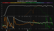
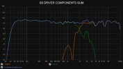
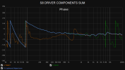
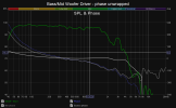
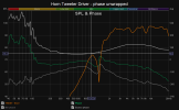
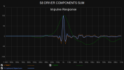
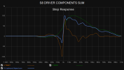
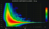
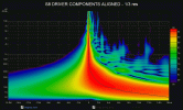
Measured my "linear phase" Sceptre S8 coax monitors in the extreme (8 cm?) nearfield some time ago. I figured one might glean some idea by looking at what the (internally DSP equalized) individual driver components and final aligned sum of a speaker could look like (on-axis) if examined within REW:

S8 DRIVER COMPONENTS ALIGN 1.png S8 DRIVER COMPONENTS ALIGN 2.png S8 DRIVER COMPONENTS ALIGN 3.png S8 DRIVER COMPONENTS ALIGN 4.png S8 DRIVER COMPONENTS ALIGN 5.png S8 DRIVER COMPONENTS ALIGN 6.png S8 DRIVER COMPONENTS ALIGN 7.png S8 DRIVER COMPONENTS ALIGN 8.gif S8 DRIVER COMPONENTS ALIGN 9.gif

*aligned this using REW's 'alignment tool' and performed manual time offset adjustments since I did not have an acoustic reference set for these measurements.
 
Last edited:

thorvat

Senior Member
Joined
Aug 9, 2021
Messages
323
Likes
387
For phase equalization and xo design, a vector average seems obvious... but do we smooth, window and/or gate the responses first? Well, personally, I normally don't.

Time align all the IRs to what reference point exactly? Which acoustic timing reference?

"Auto" align the IR start time?

Vector average indeed is the right choice, but using multiple measurements in phase correction isn't necessary as with amplitude correction because phase doesn't vary that much depending on the position.

"Auto" aligning the IR start time is a good idea when doing phase correction. Using acoustic reference is necessaray only when time-aligning sub to your speaker.

Phase correction requires 2 measurements, depending on what you are correcting.
When correcting speaker's phase response it is recommended to put your speaker at the center of the room and measure it from small distance (50-100cm), so that reflections are minimized.
When correcting phase of LF spectrum to avoid cancelations between speakers you measure each speaker from your LP.
 
Last edited:
Top Bottom