BLOWN/BUSTED Definitive Technology (Def Tech) BP7006/BP7004/BP7002 Amp Module? - Read On (BP8954MOD)
so i stumbled into some bp7006s in a nice package deal
i tested them in person only to find that the output on one of them was limited, and the other appeared fine
upon further inspection when i got them home, i realized they were both having some output issues. one was like '50%' output, the other, barely made any noise
called def tech after numerous reports on how good their support was, i was deflated to find out how poor their support now is. despite numerous folks reporting they have been replacing failed BP amps at no cost, and even polls taken from owners showing almost a 50% failure rate, they refused to take ownership of the issue. quoted me at 200/ea to replace, and after fighting tooth and nail only offered a 25% discount. and this is to replace the busted modules with the SAME design, not even a new and improved design offering more reliability. f that, sucks when a company falls from doing the right thing in the name of profit
rant over, anyway, i searched the interwebs only to find someone who suggested replacing a bank of caps that are a frequent issue. i performed that fix, and to no avail, the output was still limited. i suspect the main caps, but the continued guessing game will get costly
so i searched for a different solution. after inspecting the toroidal transformers, i learned we had dual 24v and 49.5v AC leads to work with
the 49.5v leads would have been great, but ultimately as the voltage goes up, so does the cost. the ~66-68VDC that would have produced would have required some beefy rectifier boards, added cost, and space. and as the power went up on the amp modules, the cost did as well
i figured i didnt need that of power to push these 4ohm woofers in the BP7006s, plus i really didnt know the VA rating of the transformer
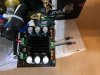
enter, the TDA8954 (picked up this one (x2), a whopping < $20/module): https://www.ebay.com/itm/US-TDA8954...o-Amplifier-Board-Core-BTL-Class/303086477878
while most of the ebay posts indicate this is 4ohm BTL stable, the spec sheet says otherwise. however since we are only bring ~32VDC to the table and they are rated to 41VDC, 80% capacity should be enough to ensure they dont overload/overheat.
the only spec i could find on input sensitivity indicated 1.4v, most AVRs should be able to supply enough voltage to run the board without needing a pre-amp/pot stage. maybe as this MOD evolves, someone can work something more exotic into the picture
it already has the power supply baked into the board, so all you needed to bring to the table was the 24VAC leads, awesome. plug and play
the entire MOD should run $30-$40/ea speaker depending on how many parts you have lying around
and the obvious downside, you'll lose the ability to power it with speaker line inputs. honestly, while the manual suggests hooking them up this way, most professionals frown against it. there is greater control to be had using them in an LFE capacity and letting the AVR control the bass management. i suspect when the manual was written, bass management may not have been as mature? who knows. if you really needed that, we could build a small circuit to handle, but that goes beyond my skillset
you'll need:
(2) RCA female inputs (ebay, 7bucks for like 5 pairs, make sure they come with nylon/plastic spacers)
(2) Bread board/ .25"/.125" wood/peg board....whatever
(2) TDA8954 amp modules
(8) Standoffs of some kind for the amp board
Spade/Quick Connect connectors/crimp connectors (assorted depending on how you wire it up)
Soldering iron
Wire
RTV/Silicon
Sockets/Wrenches (metric)
Screw drivers
REMOVE THE PLATE
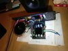
first we need to remove the plate from the speaker. disconnect the 11 outer perimeter screws from the plate. take a flat head and pry the edges, work your way around the plate prying little by little while also pulling up on the power cord (it's fine, it can take some pulling). eventually it will separate from the box and pull out
disconnect the speaker leads from the plate. you'll have two leads that connect to the speaker inputs (these are the upper speaker arrays), and two leads that connect directly to the amp module (goes to the woofer)
REMOVE THE AMP MODULE
the speaker input leads have a wire running from them, to the amp module. using a socket, remove the nut, washer, spade terminal/tab, and then the ring connector that the wire is connected to. put the spade terminal, washer, and nut back on. do this one at a time, one of the spade connectors is fatter than the other, so just make sure you're paying attention if you do them both at the same time before you put it back together
remove the input sensitivity knob (potentiometer, pot). place two flat heads under each side of the knob, pry up, it will pop off with some force. take a socket and remove the nut under the knob
find the power connector from the transformer to the amp board. it likely has some glue crap to hold it in place, just hack away at that glue with a flat head, push the tab, and pull up to disconnect
remove the screw that is right next to the RCA input
remove the two screws that hold the head sink to the plate (not the triangular brace between the transformer and amp module)
remove the two screws under the amp board that hold it to the triangular brace
optionally, you can remove the two screws that hold the triangular brace to the plate as you can always replace it later. we use this to mount our new board to
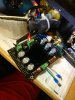
NOW the fun part, disconnecting the amp from the f'in glue. honestly, there really isn't an easy way to do this other than just prying and rocking. get a flat head under any spot you can, and start prying up, little by little. apply some force to the board in all directions, up down left right, pull side to side...etc. just keep working your flat head around until you can get it under the board and apply more and more leverage. the two troubled areas will be the RCA input, and the LED. if the LED breaks off, thats fine, one less hole to seal later. the glue should be very rigid, so it will crack and break eventually, just be patient. it will separate
i think thats it, you should now be left with just the speaker terminal inputs, the triangular brace, the transformer, and possibly an LED the ripped from the board") (like me, ha)
(like me, ha)
MOUNT THE NEW MODULE
solder up your RCA jack, and mount it to the chassis
RTV/Silicon the following: LED hole, screw hold next to the RCA input, potentiometer/pot hole (i luckily found a plastic plug that i jammed in there, but then sealed with some RTV), and the two screw holes that held the heat sink
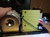
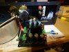
well, this is where you all can get creative. however the hell you plan to mount the board is entirely up to you. i personally used the existing triangular brace to mount a 3"x5" bread board. i had to drill one hole that didnt line up to accept a M3 screw (use a 1/8" or #31/220 bit)
i then used the same bit to drill out the stand off holes as mine were also M3 sized. mounted the amp to the board
i ran two little wire leads from the speaker output from the board and crimped two male spade connectors for quick connecting the sub
hook in your RCA leads into the amp module
POWER DELIVERY
you have two options here, depending on how much wire you leave and where you cut to get to your amp module
if your amp module is going to be super close to where the old wire leads went, you can actually remove the wire from the plastic connector to maximize the wire lead. take a small flat head, and put down on the metal tabs holding the wire into the connector. then you can cut, strip, and wire directly into the power input of the amp
if not, just cut em whereever and crimp some new leads to it and bring it to your amp module
we are looking for the WHITE lead (GND) and the two RED leads (24v). connect those to the respective inputs on the amp board. the BLUE lines are the 49.5V and we will not be using, properly end cap them
HOOK IT UP
before you do this, do a quick test if possible. use your cell phone or whatever and a random speaker to ensure everything is working before sealing it back into the box
when ready,
take the wire pair that has the red wire, and hook that onto the speaker inputs
the black and white pair is the one that goes to the new amp module, white is pos(+), black is neg(-)
screw it back together, enjoy
honestly, this is a quick, inexpensive, and fairly easy MOD most people can do without shelling out the hundreds of getting more modules that have the same likelihood of dying again
i'm sure there is tons of room for improvement, so maybe someone will come up with an alternative or V2. perhaps a tone control board/pot, or some other module that takes advantage of the 49.5V leads
for now, this module can literally bottom out the radiators (whoops) in my testing. while my AVR set it to +3.5dB on the sub, i had to lower it to -4dB to keep it under control, so plenty of power is available
so i stumbled into some bp7006s in a nice package deal
i tested them in person only to find that the output on one of them was limited, and the other appeared fine
upon further inspection when i got them home, i realized they were both having some output issues. one was like '50%' output, the other, barely made any noise
called def tech after numerous reports on how good their support was, i was deflated to find out how poor their support now is. despite numerous folks reporting they have been replacing failed BP amps at no cost, and even polls taken from owners showing almost a 50% failure rate, they refused to take ownership of the issue. quoted me at 200/ea to replace, and after fighting tooth and nail only offered a 25% discount. and this is to replace the busted modules with the SAME design, not even a new and improved design offering more reliability. f that, sucks when a company falls from doing the right thing in the name of profit
rant over, anyway, i searched the interwebs only to find someone who suggested replacing a bank of caps that are a frequent issue. i performed that fix, and to no avail, the output was still limited. i suspect the main caps, but the continued guessing game will get costly
so i searched for a different solution. after inspecting the toroidal transformers, i learned we had dual 24v and 49.5v AC leads to work with
the 49.5v leads would have been great, but ultimately as the voltage goes up, so does the cost. the ~66-68VDC that would have produced would have required some beefy rectifier boards, added cost, and space. and as the power went up on the amp modules, the cost did as well
i figured i didnt need that of power to push these 4ohm woofers in the BP7006s, plus i really didnt know the VA rating of the transformer
enter, the TDA8954 (picked up this one (x2), a whopping < $20/module): https://www.ebay.com/itm/US-TDA8954...o-Amplifier-Board-Core-BTL-Class/303086477878
while most of the ebay posts indicate this is 4ohm BTL stable, the spec sheet says otherwise. however since we are only bring ~32VDC to the table and they are rated to 41VDC, 80% capacity should be enough to ensure they dont overload/overheat.
the only spec i could find on input sensitivity indicated 1.4v, most AVRs should be able to supply enough voltage to run the board without needing a pre-amp/pot stage. maybe as this MOD evolves, someone can work something more exotic into the picture
it already has the power supply baked into the board, so all you needed to bring to the table was the 24VAC leads, awesome. plug and play
the entire MOD should run $30-$40/ea speaker depending on how many parts you have lying around
and the obvious downside, you'll lose the ability to power it with speaker line inputs. honestly, while the manual suggests hooking them up this way, most professionals frown against it. there is greater control to be had using them in an LFE capacity and letting the AVR control the bass management. i suspect when the manual was written, bass management may not have been as mature? who knows. if you really needed that, we could build a small circuit to handle, but that goes beyond my skillset
you'll need:
(2) RCA female inputs (ebay, 7bucks for like 5 pairs, make sure they come with nylon/plastic spacers)
(2) Bread board/ .25"/.125" wood/peg board....whatever
(2) TDA8954 amp modules
(8) Standoffs of some kind for the amp board
Spade/Quick Connect connectors/crimp connectors (assorted depending on how you wire it up)
Soldering iron
Wire
RTV/Silicon
Sockets/Wrenches (metric)
Screw drivers
REMOVE THE PLATE
first we need to remove the plate from the speaker. disconnect the 11 outer perimeter screws from the plate. take a flat head and pry the edges, work your way around the plate prying little by little while also pulling up on the power cord (it's fine, it can take some pulling). eventually it will separate from the box and pull out
disconnect the speaker leads from the plate. you'll have two leads that connect to the speaker inputs (these are the upper speaker arrays), and two leads that connect directly to the amp module (goes to the woofer)
REMOVE THE AMP MODULE
the speaker input leads have a wire running from them, to the amp module. using a socket, remove the nut, washer, spade terminal/tab, and then the ring connector that the wire is connected to. put the spade terminal, washer, and nut back on. do this one at a time, one of the spade connectors is fatter than the other, so just make sure you're paying attention if you do them both at the same time before you put it back together
remove the input sensitivity knob (potentiometer, pot). place two flat heads under each side of the knob, pry up, it will pop off with some force. take a socket and remove the nut under the knob
find the power connector from the transformer to the amp board. it likely has some glue crap to hold it in place, just hack away at that glue with a flat head, push the tab, and pull up to disconnect
remove the screw that is right next to the RCA input
remove the two screws that hold the head sink to the plate (not the triangular brace between the transformer and amp module)
remove the two screws under the amp board that hold it to the triangular brace
optionally, you can remove the two screws that hold the triangular brace to the plate as you can always replace it later. we use this to mount our new board to
NOW the fun part, disconnecting the amp from the f'in glue. honestly, there really isn't an easy way to do this other than just prying and rocking. get a flat head under any spot you can, and start prying up, little by little. apply some force to the board in all directions, up down left right, pull side to side...etc. just keep working your flat head around until you can get it under the board and apply more and more leverage. the two troubled areas will be the RCA input, and the LED. if the LED breaks off, thats fine, one less hole to seal later. the glue should be very rigid, so it will crack and break eventually, just be patient. it will separate
i think thats it, you should now be left with just the speaker terminal inputs, the triangular brace, the transformer, and possibly an LED the ripped from the board
(like me, ha)MOUNT THE NEW MODULE
solder up your RCA jack, and mount it to the chassis
RTV/Silicon the following: LED hole, screw hold next to the RCA input, potentiometer/pot hole (i luckily found a plastic plug that i jammed in there, but then sealed with some RTV), and the two screw holes that held the heat sink
well, this is where you all can get creative. however the hell you plan to mount the board is entirely up to you. i personally used the existing triangular brace to mount a 3"x5" bread board. i had to drill one hole that didnt line up to accept a M3 screw (use a 1/8" or #31/220 bit)
i then used the same bit to drill out the stand off holes as mine were also M3 sized. mounted the amp to the board
i ran two little wire leads from the speaker output from the board and crimped two male spade connectors for quick connecting the sub
hook in your RCA leads into the amp module
POWER DELIVERY
you have two options here, depending on how much wire you leave and where you cut to get to your amp module
if your amp module is going to be super close to where the old wire leads went, you can actually remove the wire from the plastic connector to maximize the wire lead. take a small flat head, and put down on the metal tabs holding the wire into the connector. then you can cut, strip, and wire directly into the power input of the amp
if not, just cut em whereever and crimp some new leads to it and bring it to your amp module
we are looking for the WHITE lead (GND) and the two RED leads (24v). connect those to the respective inputs on the amp board. the BLUE lines are the 49.5V and we will not be using, properly end cap them
HOOK IT UP
before you do this, do a quick test if possible. use your cell phone or whatever and a random speaker to ensure everything is working before sealing it back into the box
when ready,
take the wire pair that has the red wire, and hook that onto the speaker inputs
the black and white pair is the one that goes to the new amp module, white is pos(+), black is neg(-)
screw it back together, enjoy
honestly, this is a quick, inexpensive, and fairly easy MOD most people can do without shelling out the hundreds of getting more modules that have the same likelihood of dying again
i'm sure there is tons of room for improvement, so maybe someone will come up with an alternative or V2. perhaps a tone control board/pot, or some other module that takes advantage of the 49.5V leads
for now, this module can literally bottom out the radiators (whoops) in my testing. while my AVR set it to +3.5dB on the sub, i had to lower it to -4dB to keep it under control, so plenty of power is available