
A few weeks ago, I published a long thread on a Spanish forum about some of the work I did some time ago, as a distraction to make the quarantine more bearable.
I have decided to post it here if you like. I suppose someone will be distracted for a while, if only by looking at the photos. There are things that may seem interesting to you.
I have copied and pasted a lot of translator text and adjusted formats, I hope I am wrong as little as possible.
The original thread is Spanish is here:
http://www.auriculares.org/foro/index.php/topic,19560.0.html
And it started like this .....
First of all, I wish to encourage everyone affected by the pandemic and express my appreciation for the efforts of so many people to combat it. I hope that at least as much suffering will help us to be better prepared from now on.
That said, for all those who have nothing better to do right now and want to entertain themselves with something, I am going to show you some photos of the things I have been doing for a while.
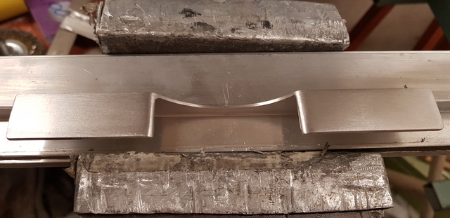
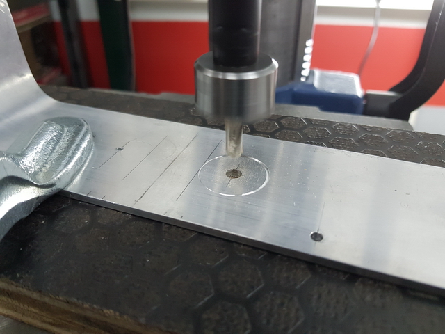
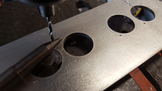
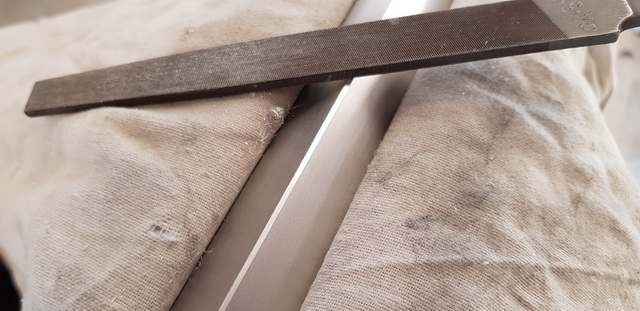
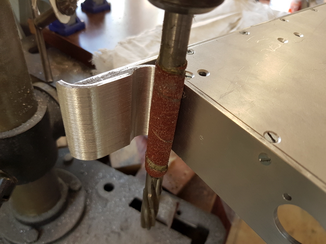
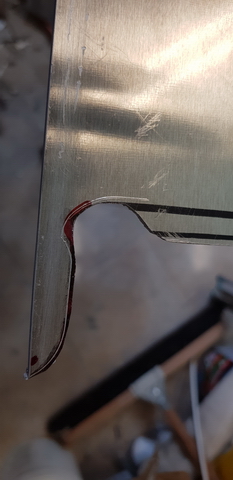
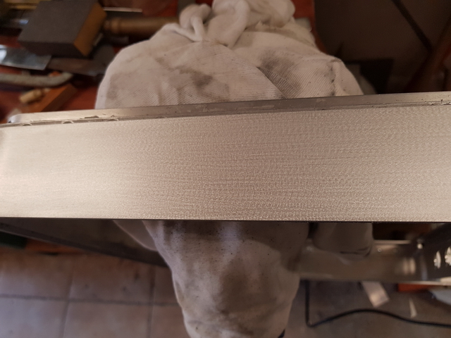
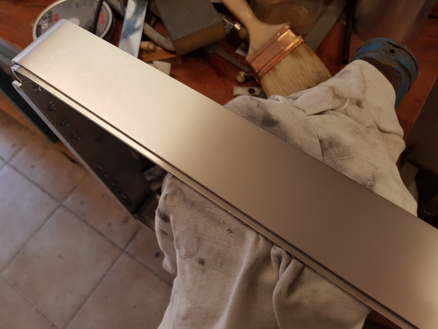
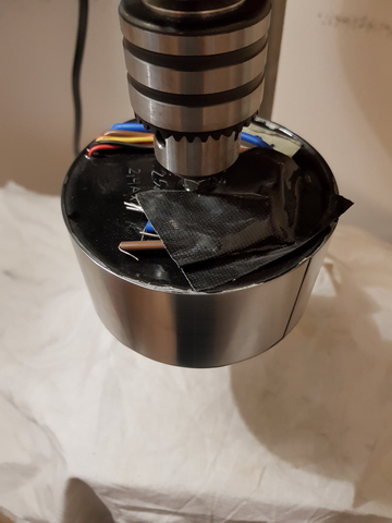
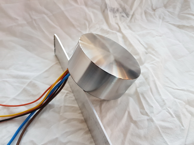
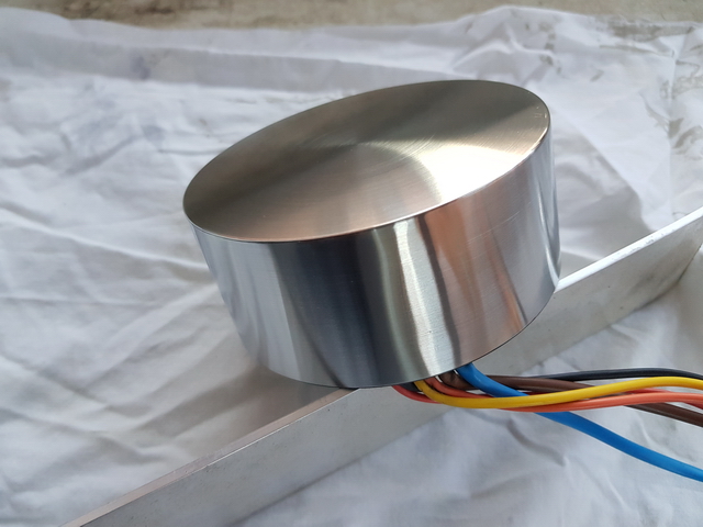
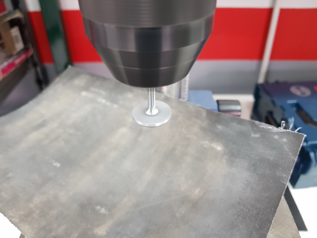
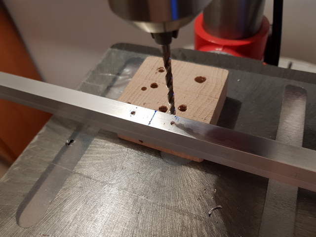
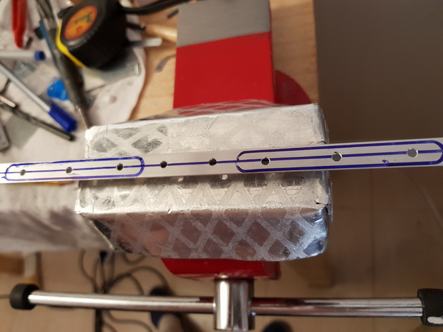
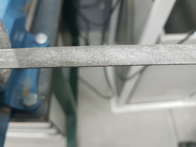
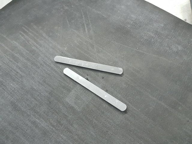
I will also explain how I have built them with a lot of photos. Not in detail because it would be a lot to explain and I don't have photos of everything either. I have tried with variations of the same assembly, welding aluminum, I have come to encapsulate a transformer, disassemble some R-core, apply varnish to the metal with results that I did not like, modify power supplies, equipment, tests, etc. But more or less with the photos that I will put, you can make one a general idea.
Rather out of enjoyment than necessity, since I was little I liked to build, dismantle or repair, things related to the theme that I was interested in at the time and although it may seem absurd, I feel a certain affinity, attachment ... I would not know how to express it, with almost any device, because I value the work that its design and construction have, however humble it is.
I remember as a young man, how some friends broke a walkman with blows to the ground ... and everyone laughed except me
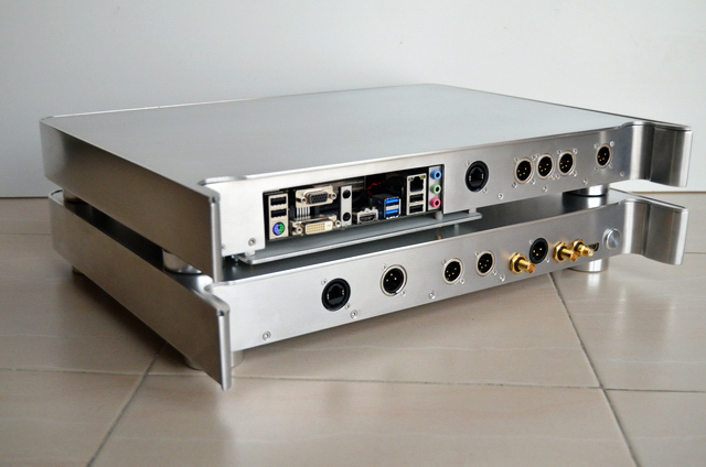
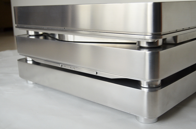
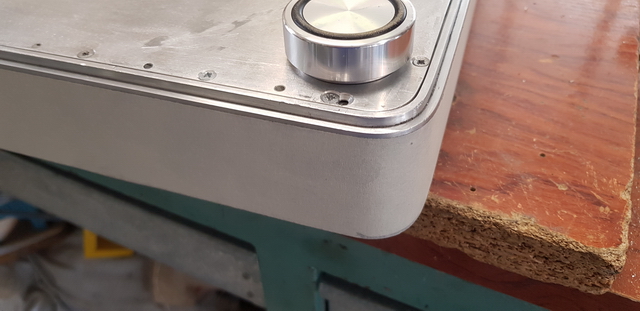
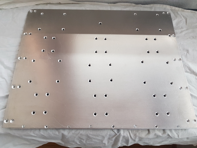
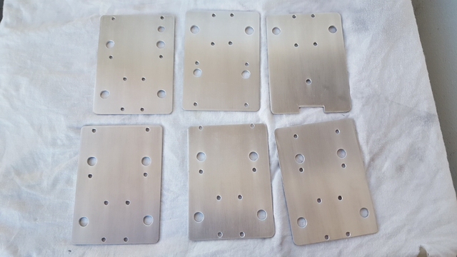
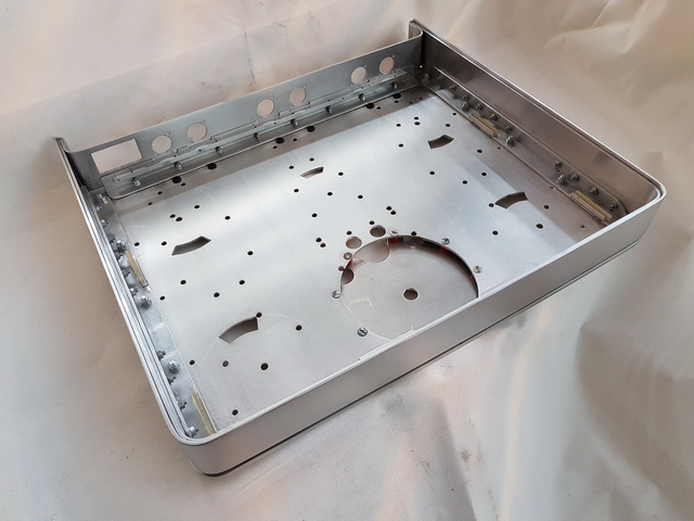
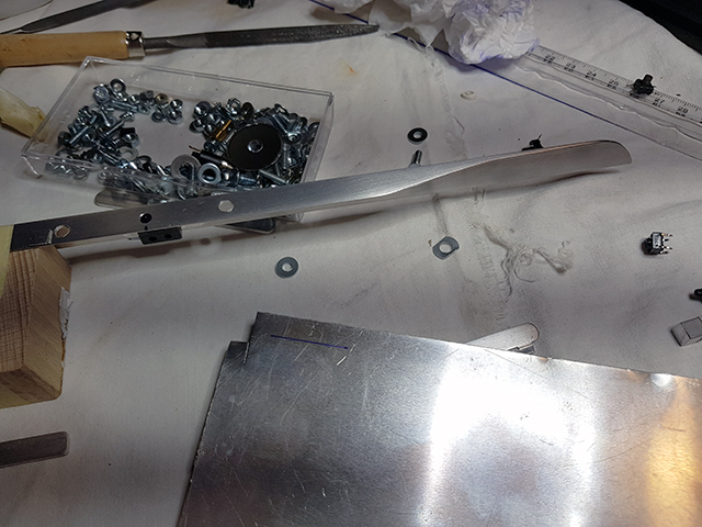
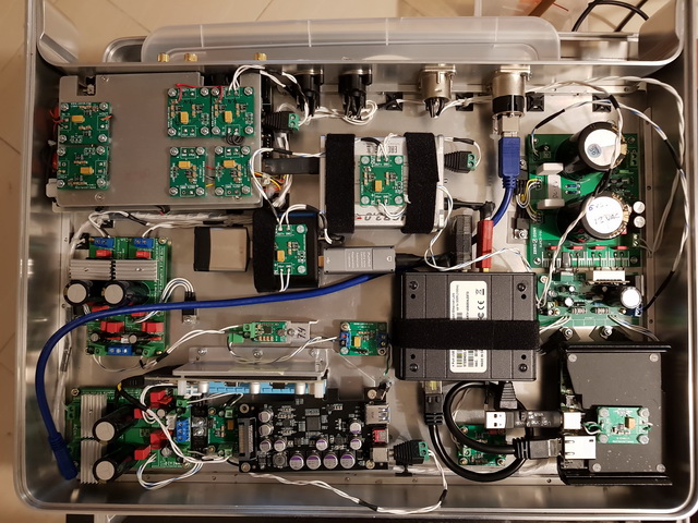
Lately as I am interested with home audio, I have always been really together with music, I decided to build what I teach you now. They are three aluminum boxes to mount a digital source that incorporates a PC, a digital converter, several USB conditioners that I have been testing, power supplies for all of them, including amplifier and DAC and a lot of low noise voltage regulators.
I have been putting all these components together for a while and decided to sort them in some way with these boxes.
Currently much of the utility of the entire system is relative. I mean, in some DACs it may or may not be convenient to use, for example, a digital converter, if the USB input is not up to the rest of the inputs of our DAC and we use a PC as a digital source, as in my case. As an example are the NAD M51 whose USB input is one of the worst of its inputs and for which I assembled all this shed and the other example is a Topping D90, much more modern , to which only any cheap USB cable that we have thrown around the house is enough for it, to even surpass the M51 with a certain amount of ease with all this mounted shed. Awesome. I hope to talk about it in another thread.
Beyond the greater or lesser real utility and the work and effort involved in doing it by hand, it has compensated me because it is something that I like, deep down I think that in part, it is an excuse ... The case is that it entertains me and I take it as a challenge to do this or that thing or detail that I imagine and being able to achieve it is a satisfaction. Although that does not always happen, my imagination is always ahead of my ability or means and sometimes it can be frustrating not to achieve it as one wants things to stay.
I think that it is not necessary to explain in detail everything related to food, it is really what I have found most difficult to configure given the good number of elements, fed at different voltages, different consumption needs and isolate some elements from others as much as possible as far as food is concerned.
As for the data, seeing more or less the elements, you can get an idea. Some of them are more or less irrelevant to the final result, but the fact is that since I have been accumulating them, at least it is the combination that has convinced me the most.
I think that after all, if not everything, at least almost all the advantages that I have seen with this montage regarding sound quality, have to do with the correct power supply and the reduction of the leak loops and not so much for the data itself or the Jitter. Except for the use of the USB / AES-EBU converter with a much more modern XMOS USB transceiver and something else.
A PC, with its digital electronics with its sudden variations in voltage, current and at such high frequencies, processors, memory, etc. They can be a good generator of electrical noise of different types. And perhaps the least important, because it is the easiest to limit, is the electrical noise in the direct voltage of the USB outputs.
The ground points, chassis, the masses and the power supply phase and neutral, are also contaminated with this generated noise and in these cases, it is no longer so easy to eliminate.
If we add to this that each equipment generates its own earth leakage currents, DAC, amplifier, etc. When we connect them between them with the audio signal cables, especially if it is not balanced wiring for example, this signal can be affected by these currents that circulate between components, through the masses of the signal cables themselves.
Ideally, the taps / ground points would be a perfect "drain" to drain all these currents. And the ground points, perfect voltage reference points for the correct operation of the rest of the analog and digital electronics, but in reality this is not the case and there may even be quite large voltage differences between different points of ground in a building for example or if they are defective. In non domestic installations, I have personally suffered significant shocks when connecting a simple HDMI cable.
Depending on which audio components, equipment chassis, ground points, and power and signal masses, may be linked in some way. The case of the M51 for example. Normally there shouldn't be too many problems, but sometimes and in the worst cases, it could worsen the audio quality or generate perfectly audible noises.
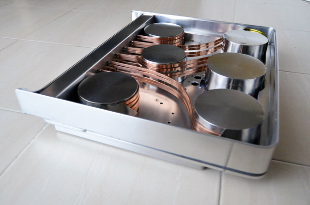
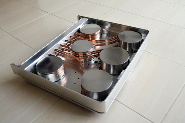
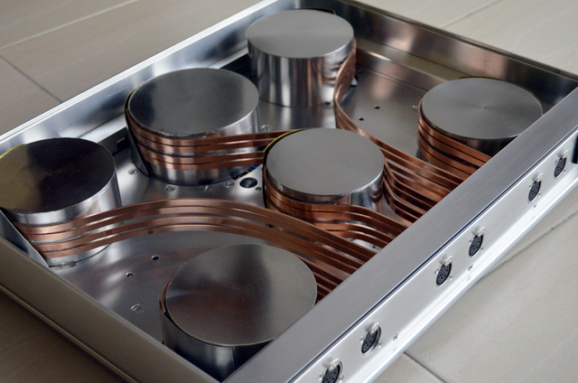
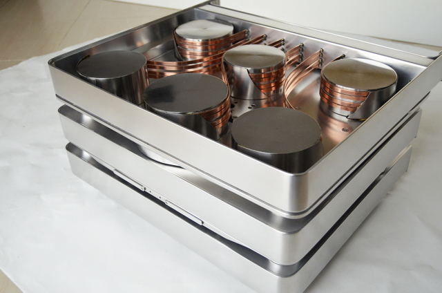
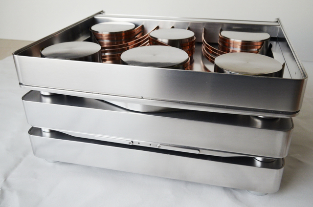
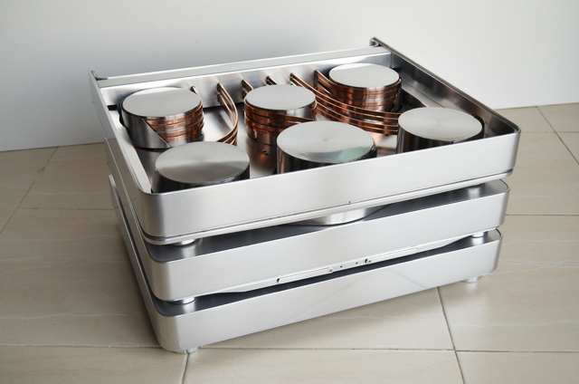
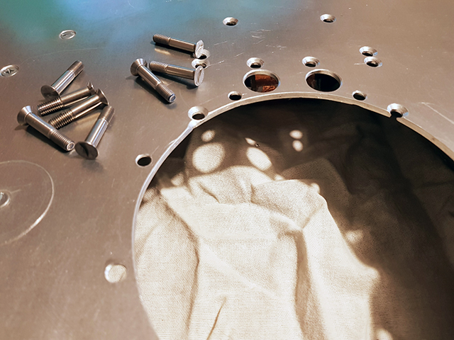
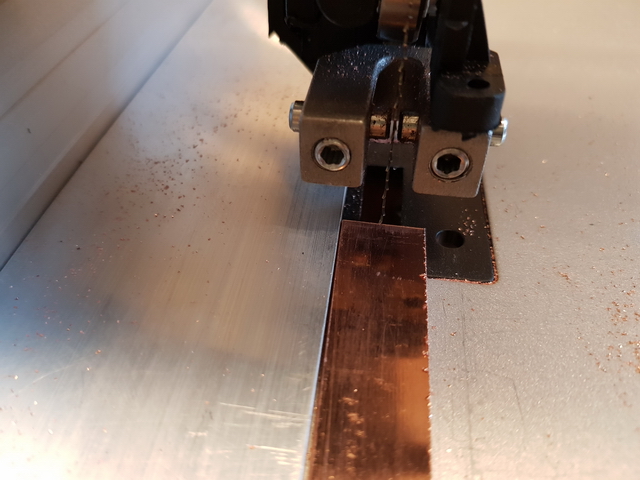
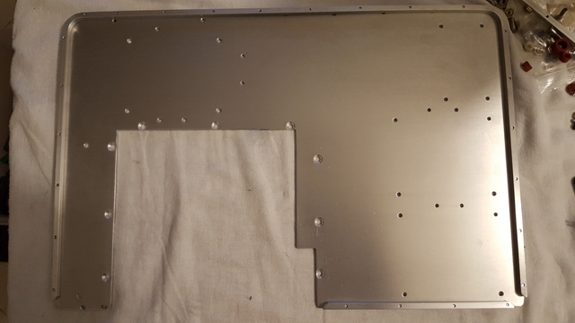
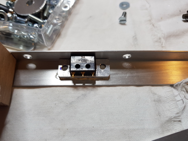
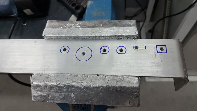
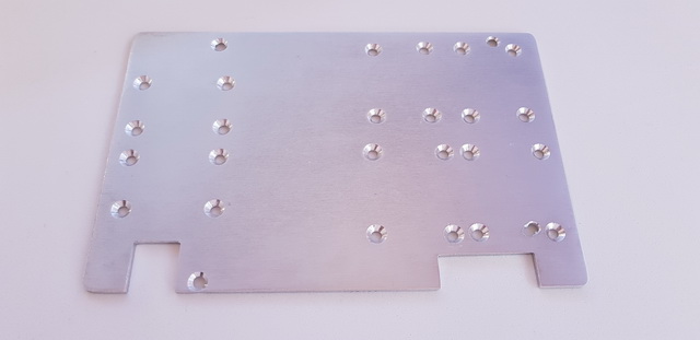
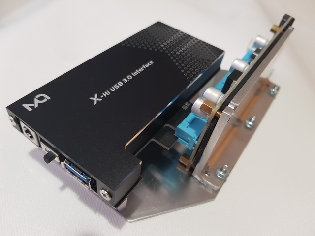
Let's go there, I'm going to roll up ... I start with the box with the transformers. The copper plates are the secondary outputs, two for each transformer. 2 of 15V, 2 of 18V, 24V and 12V seems to me to remember. The entrances are on the inside.

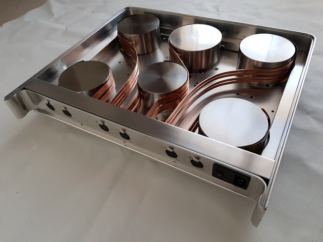


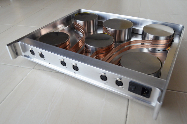

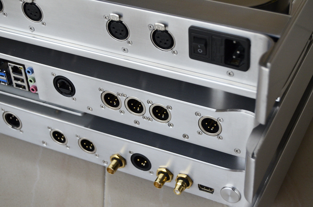
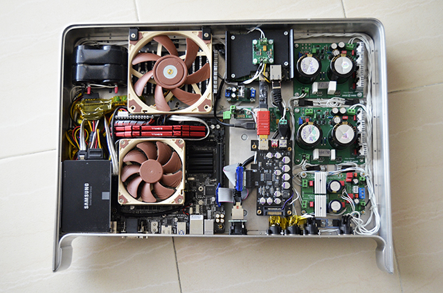
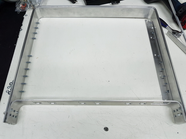
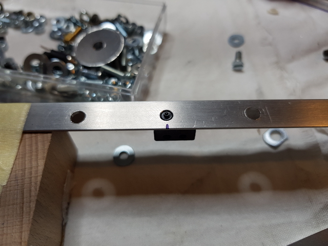
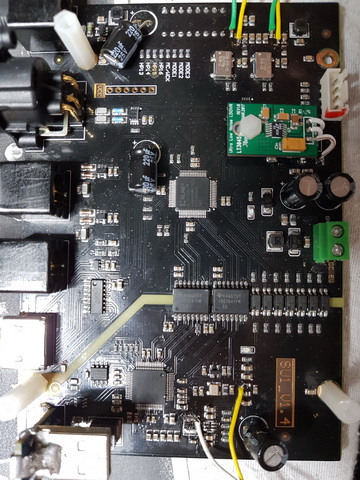
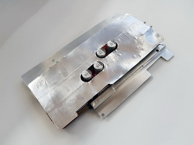
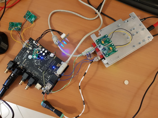
In this box is the digital converter and part of the USB and ethernet network. Also various power supplies and voltage regulators.
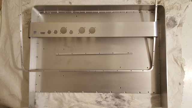
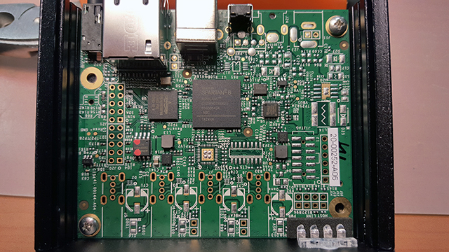
The front of the PC case with the power buttons, reset and the power and activity LEDs of the SSD.

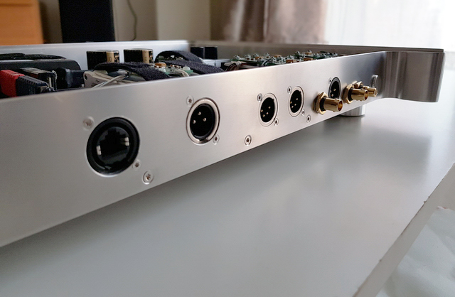
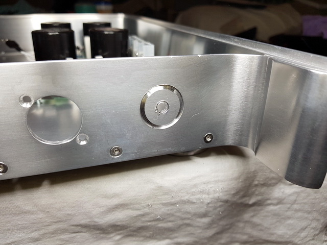
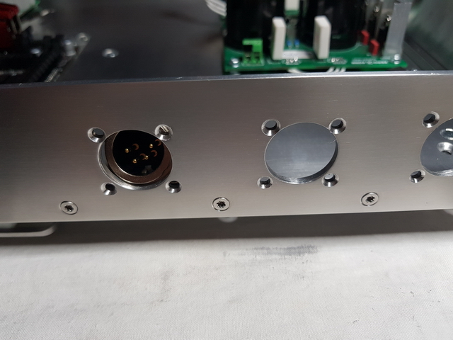
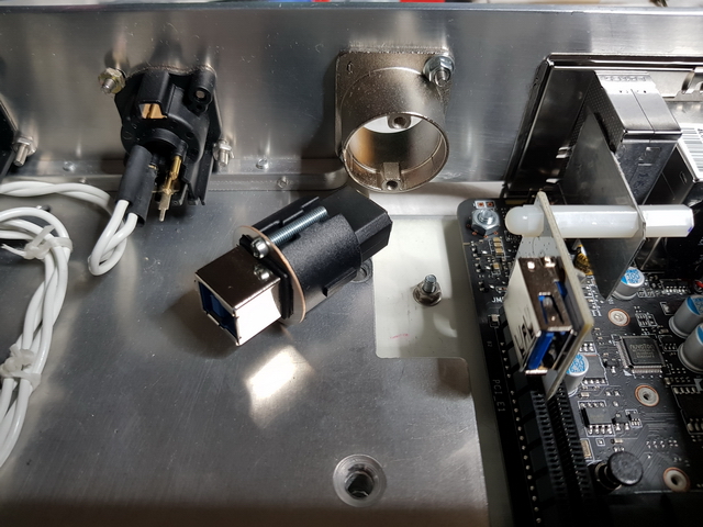
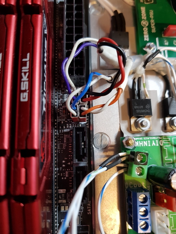
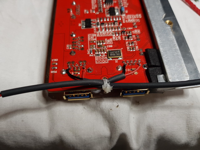
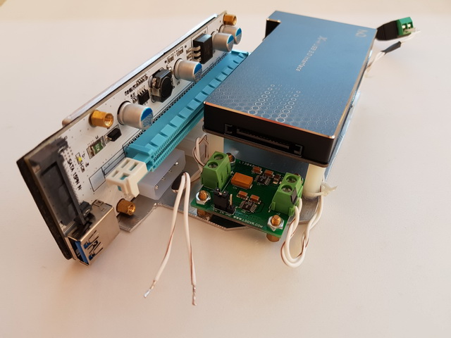
Back of the same box. You can see the back of the motherboard, ethernet connections and power inputs and outputs for for example the HDVD800 headphone amp that requires + -18Vcc.


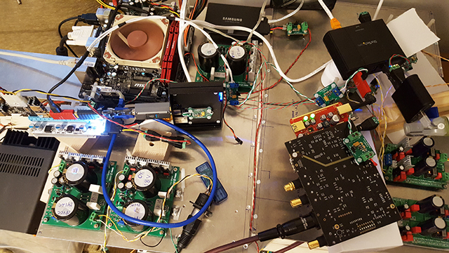
Part of the set under test. The switched mode power supplies of the M51 and HDVD800 are unmounted and I supplied them with DC power. I also have photos of the process, perhaps later I will explain these modifications as well.

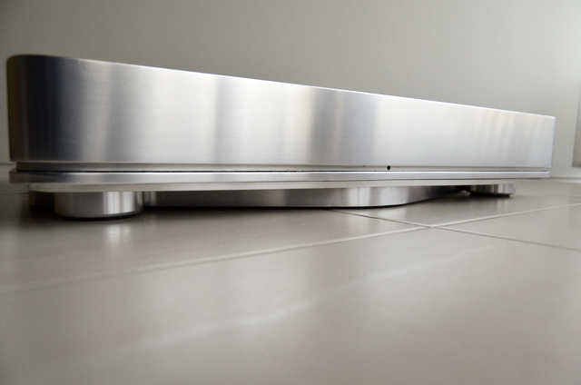
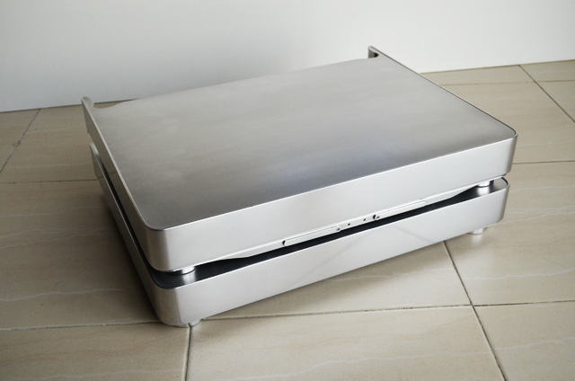
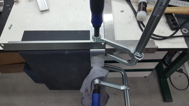
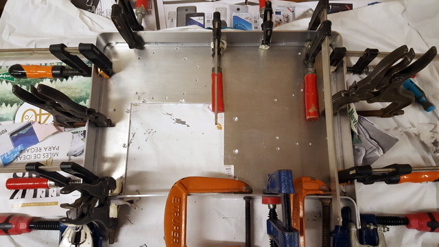
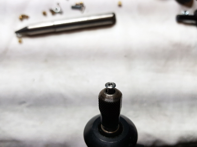
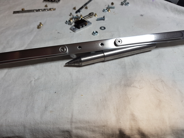
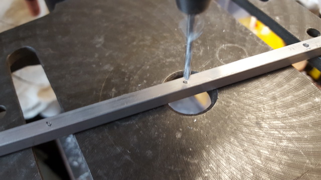
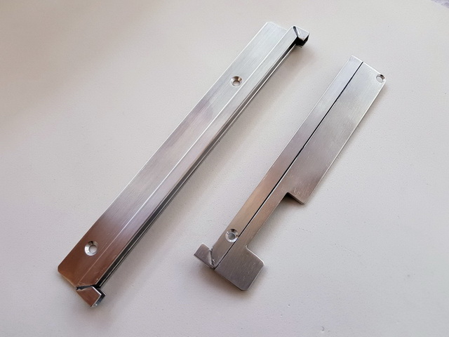
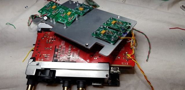
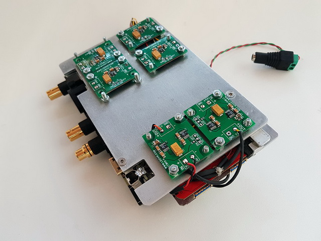
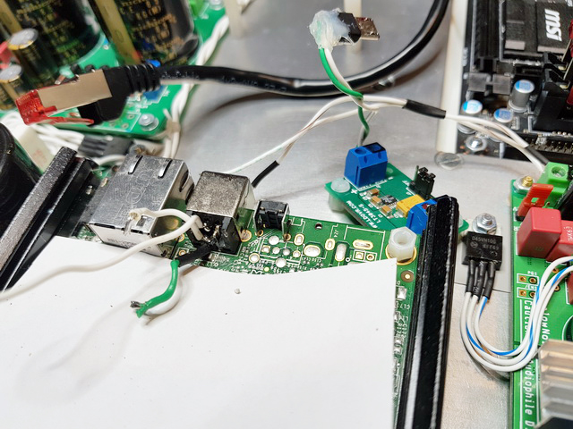
The montage has always been changing in one way or another. You may see things in photos that you do not see in others, even if they belong to the same box.


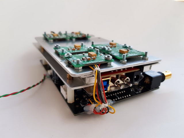
This is a photo of the first test assembly and very happy with the result.
Although they do not have to do with audio, I also put a photo of a liquid cooling block for computers, to which I was dedicated some time many years ago. I was setting up a system to measure temperatures, flow, pressure, etc. With that I enjoyed, learned and have good memories of that time. I'm surprised that the web, http://www.devilmaster.org/, remain active after almost 20 years.
This is a photo of a waterblock that I built back then.

I will leave you some more links below all this.
My Nick in forums at the time was dnkroz and you can read an article about its construction here:
http://www.devilmaster.org/sections.php?op=viewarticle&artid=18
You can see a gallery with more photos through this link:
http://www.devilmaster.org/modules.php?name=coppermine&file=thumbnails&album=65
And the start of the thread before its construction here:
http://www.devilmaster.org/forums/viewtopic.php?t=94&postdays=0&postorder=asc&start=0
Here another gallery of another block that I also made at the time
http://www.devilmaster.org/modules.php?name=coppermine&file=thumbnails&album=23
There are things that you find interesting to know about liquid cooling for computers. Processor temperature measurements in real time, through the reading of the internal diode of the internal core. Temperature variations of several degrees in msec, specific temperature patterns in time for each program executed, that is, just by looking at the temperature graph, it is possible to know what program that processor has executed.
Also measurements of flow, pressure in different points, air and water temperature at 7 different points with a resolution of 0.01ºC ... Anyway, a study of the operation of a refrigeration system to see for example how X watts a processor generates or the water pump itself, dissipate in it and in turn into the air. Influence of flow, static pressure, pressure differences throughout the circuit, variations in pressure related to the rotation of the pump, calculation of the energy dissipated by friction, etc.
I learned and really enjoyed it all.
The pity is that the second part with practical examples, I never got to finish it. I ended up reluctantly reading what was said in some forums at the time regarding this topic ... Anyway.
Data acquisition and liquid cooling. Part I
http://www.devilmaster.org/sections.php?op=viewarticle&artid=44
And the start of the thread in the forum:
http://www.devilmaster.org/forums/viewtopic.php?t=472

I have decided to post it here if you like. I suppose someone will be distracted for a while, if only by looking at the photos. There are things that may seem interesting to you.
I have copied and pasted a lot of translator text and adjusted formats, I hope I am wrong as little as possible.
The original thread is Spanish is here:
http://www.auriculares.org/foro/index.php/topic,19560.0.html
And it started like this .....
First of all, I wish to encourage everyone affected by the pandemic and express my appreciation for the efforts of so many people to combat it. I hope that at least as much suffering will help us to be better prepared from now on.
That said, for all those who have nothing better to do right now and want to entertain themselves with something, I am going to show you some photos of the things I have been doing for a while.
I will also explain how I have built them with a lot of photos. Not in detail because it would be a lot to explain and I don't have photos of everything either. I have tried with variations of the same assembly, welding aluminum, I have come to encapsulate a transformer, disassemble some R-core, apply varnish to the metal with results that I did not like, modify power supplies, equipment, tests, etc. But more or less with the photos that I will put, you can make one a general idea.
Rather out of enjoyment than necessity, since I was little I liked to build, dismantle or repair, things related to the theme that I was interested in at the time and although it may seem absurd, I feel a certain affinity, attachment ... I would not know how to express it, with almost any device, because I value the work that its design and construction have, however humble it is.
I remember as a young man, how some friends broke a walkman with blows to the ground ... and everyone laughed except me
Lately as I am interested with home audio, I have always been really together with music, I decided to build what I teach you now. They are three aluminum boxes to mount a digital source that incorporates a PC, a digital converter, several USB conditioners that I have been testing, power supplies for all of them, including amplifier and DAC and a lot of low noise voltage regulators.
I have been putting all these components together for a while and decided to sort them in some way with these boxes.
Currently much of the utility of the entire system is relative. I mean, in some DACs it may or may not be convenient to use, for example, a digital converter, if the USB input is not up to the rest of the inputs of our DAC and we use a PC as a digital source, as in my case. As an example are the NAD M51 whose USB input is one of the worst of its inputs and for which I assembled all this shed and the other example is a Topping D90, much more modern , to which only any cheap USB cable that we have thrown around the house is enough for it, to even surpass the M51 with a certain amount of ease with all this mounted shed. Awesome. I hope to talk about it in another thread.
Beyond the greater or lesser real utility and the work and effort involved in doing it by hand, it has compensated me because it is something that I like, deep down I think that in part, it is an excuse ... The case is that it entertains me and I take it as a challenge to do this or that thing or detail that I imagine and being able to achieve it is a satisfaction. Although that does not always happen, my imagination is always ahead of my ability or means and sometimes it can be frustrating not to achieve it as one wants things to stay.
I think that it is not necessary to explain in detail everything related to food, it is really what I have found most difficult to configure given the good number of elements, fed at different voltages, different consumption needs and isolate some elements from others as much as possible as far as food is concerned.
As for the data, seeing more or less the elements, you can get an idea. Some of them are more or less irrelevant to the final result, but the fact is that since I have been accumulating them, at least it is the combination that has convinced me the most.
I think that after all, if not everything, at least almost all the advantages that I have seen with this montage regarding sound quality, have to do with the correct power supply and the reduction of the leak loops and not so much for the data itself or the Jitter. Except for the use of the USB / AES-EBU converter with a much more modern XMOS USB transceiver and something else.
A PC, with its digital electronics with its sudden variations in voltage, current and at such high frequencies, processors, memory, etc. They can be a good generator of electrical noise of different types. And perhaps the least important, because it is the easiest to limit, is the electrical noise in the direct voltage of the USB outputs.
The ground points, chassis, the masses and the power supply phase and neutral, are also contaminated with this generated noise and in these cases, it is no longer so easy to eliminate.
If we add to this that each equipment generates its own earth leakage currents, DAC, amplifier, etc. When we connect them between them with the audio signal cables, especially if it is not balanced wiring for example, this signal can be affected by these currents that circulate between components, through the masses of the signal cables themselves.
Ideally, the taps / ground points would be a perfect "drain" to drain all these currents. And the ground points, perfect voltage reference points for the correct operation of the rest of the analog and digital electronics, but in reality this is not the case and there may even be quite large voltage differences between different points of ground in a building for example or if they are defective. In non domestic installations, I have personally suffered significant shocks when connecting a simple HDMI cable.
Depending on which audio components, equipment chassis, ground points, and power and signal masses, may be linked in some way. The case of the M51 for example. Normally there shouldn't be too many problems, but sometimes and in the worst cases, it could worsen the audio quality or generate perfectly audible noises.
Let's go there, I'm going to roll up ... I start with the box with the transformers. The copper plates are the secondary outputs, two for each transformer. 2 of 15V, 2 of 18V, 24V and 12V seems to me to remember. The entrances are on the inside.
In this box is the digital converter and part of the USB and ethernet network. Also various power supplies and voltage regulators.
The front of the PC case with the power buttons, reset and the power and activity LEDs of the SSD.
Back of the same box. You can see the back of the motherboard, ethernet connections and power inputs and outputs for for example the HDVD800 headphone amp that requires + -18Vcc.
Part of the set under test. The switched mode power supplies of the M51 and HDVD800 are unmounted and I supplied them with DC power. I also have photos of the process, perhaps later I will explain these modifications as well.
The montage has always been changing in one way or another. You may see things in photos that you do not see in others, even if they belong to the same box.
This is a photo of the first test assembly and very happy with the result.
Although they do not have to do with audio, I also put a photo of a liquid cooling block for computers, to which I was dedicated some time many years ago. I was setting up a system to measure temperatures, flow, pressure, etc. With that I enjoyed, learned and have good memories of that time. I'm surprised that the web, http://www.devilmaster.org/, remain active after almost 20 years.
This is a photo of a waterblock that I built back then.
I will leave you some more links below all this.
My Nick in forums at the time was dnkroz and you can read an article about its construction here:
http://www.devilmaster.org/sections.php?op=viewarticle&artid=18
You can see a gallery with more photos through this link:
http://www.devilmaster.org/modules.php?name=coppermine&file=thumbnails&album=65
And the start of the thread before its construction here:
http://www.devilmaster.org/forums/viewtopic.php?t=94&postdays=0&postorder=asc&start=0
Here another gallery of another block that I also made at the time
http://www.devilmaster.org/modules.php?name=coppermine&file=thumbnails&album=23
There are things that you find interesting to know about liquid cooling for computers. Processor temperature measurements in real time, through the reading of the internal diode of the internal core. Temperature variations of several degrees in msec, specific temperature patterns in time for each program executed, that is, just by looking at the temperature graph, it is possible to know what program that processor has executed.
Also measurements of flow, pressure in different points, air and water temperature at 7 different points with a resolution of 0.01ºC ... Anyway, a study of the operation of a refrigeration system to see for example how X watts a processor generates or the water pump itself, dissipate in it and in turn into the air. Influence of flow, static pressure, pressure differences throughout the circuit, variations in pressure related to the rotation of the pump, calculation of the energy dissipated by friction, etc.
I learned and really enjoyed it all.
The pity is that the second part with practical examples, I never got to finish it. I ended up reluctantly reading what was said in some forums at the time regarding this topic ... Anyway.
Data acquisition and liquid cooling. Part I
http://www.devilmaster.org/sections.php?op=viewarticle&artid=44
And the start of the thread in the forum:
http://www.devilmaster.org/forums/viewtopic.php?t=472


")